1
\$\begingroup\$

I have encountered a situation where I need to draw 1 controlled current source on a circuit diagram with 2 inputs and 2 outputs but I'm not sure what is the proper way to convey this idea. I can't seem to find anything online either.

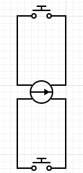
Here is what I came up with (doesn't seem proper to me):

enter image description here

How can I draw a current source with two outputs?

\$\endgroup\$
1
  • \$\begingroup\$ How does an input translate to an output? \$\endgroup\$
    – Ron Beyer
    Commented Sep 18, 2019 at 17:41

2 Answers 2

2
\$\begingroup\$

There are two different kinds of controlled current sources, they are typically drawn as shown below:

enter image description here
Source: https://www.electronics-tutorials.ws/dccircuits/current-source.html

Usually a diamond indicates a controlled/dependent source, a circle indicates a independent source.

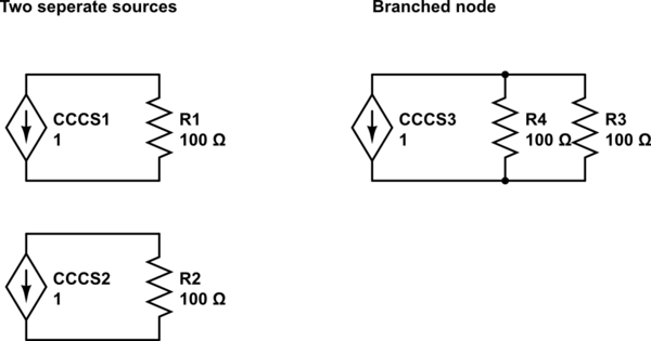
If you want to draw two outputs, here are the options for drawing. A branched node shares the current with two nodes. Two separate sources keep the current the same (and can share the same input current node for dependence)

schematic

simulate this circuit – Schematic created using CircuitLab

\$\endgroup\$
3
  • \$\begingroup\$ Alright, thanks for that part. Now this source had multiple outputs and I ended up connecting two different "devices" to it. Can I simply draw two lines coming out of the diamond instead of one? \$\endgroup\$
    – Ahm23
    Commented Sep 18, 2019 at 17:56
  • \$\begingroup\$ The current will be the same so you don't need to draw two wires coming out of a source, you can just draw a node and split the wire (if that makes sense). If you don't want the current to be split with the wire (a junction splits the current) then you'll need to draw two separate sources) \$\endgroup\$
    – Voltage Spike
    Commented Sep 18, 2019 at 17:58
  • \$\begingroup\$ YES, THAT's exactly what I was looking for. The node and split. Thank you very much. Unfortunately my rep is too low to up vote your response. \$\endgroup\$
    – Ahm23
    Commented Sep 18, 2019 at 18:18
0
\$\begingroup\$

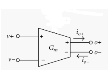
If you're talking about a VCCS I like a symbol something like this, though there are other possibilities:

enter image description here

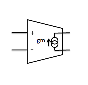
[Edit] Or hopefully less confusing now that I had time to draw my preferred symbol, though you could substitute the diamond symbol for the interlinked rings:

enter image description here

\$\endgroup\$
2
  • \$\begingroup\$ This seems confusing to me. A current source shouldn't be labeled with + and - as that implies a voltage, and we don't automatically know the orientation of a voltage for a current source. All of the symbols I have ever seen are the diamond shapes as shown by @VoltageSpike. \$\endgroup\$ Commented Sep 18, 2019 at 17:55
  • \$\begingroup\$ @ElliotAlderson Yeah, I typically would draw the current source inside the block showing the direction of current flow, but I couldn't find a symbol like that quickly. I think the + sign indicates that the current will flow in the direction shown by the arrow for positive input voltages, but I agree, it's somewhat confusing and unnecessary. Of course the textbook VCCS is what VoltageSpike showed, but I don't necessarily like the disembodied control terminals on a schematic. \$\endgroup\$
    – John D
    Commented Sep 18, 2019 at 17:58

Your Answer

By clicking “Post Your Answer”, you agree to our terms of service and acknowledge you have read our privacy policy.

Not the answer you're looking for? Browse other questions tagged or ask your own question.