2
\$\begingroup\$

Hello i am creating a circuit that uses the TPS63070 buck-boost converter. As i was looking at its sample circuit and application in the datasheet on page 18 (under Inductor Selection), i am given 4 suggested inductor values.

I dont really understand on how to use the formula given in order for me to determine what is suited for my use.

my applications is for this to control 2 motors that may draw 0.5A - 1A (variable speed) at 7.5v each.

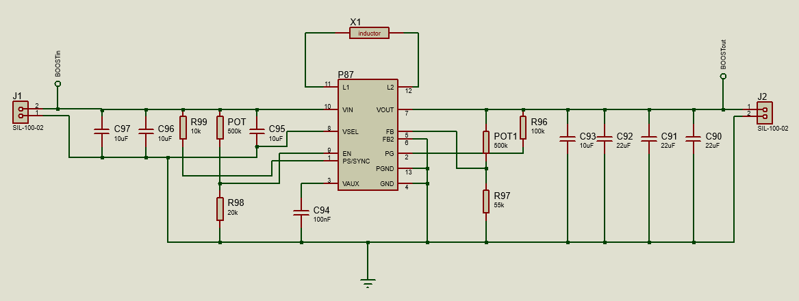
here is my circuit. Also maybe for consideration is i made the circuit so that i may adjust the under voltage cutoff protection and the output voltage. Output voltage maybe adjusted by +- 0.75v during application and undervoltage maybe adjusted by +- 0.5v.

enter image description here

So of the recommended 4 inductors

- 1.2 μH    Coilcraft,    XFL4015-122ME     4.5 A / 18.8 mΩ
- 1.5 μH    Coilcraft,    XFL4020-152ME     4.6 A / 14.4 mΩ
- 1.0 μH    Coilcraft,    XFL4020-102ME     5.4 A / 10.8 mΩ
- 1 μH      Murata,       1277AS-H-1R0M     3.7 A / 45 mΩ

which one should i pick? and if you can tell me how did you compute for it, it would greatly help me in future endeavours. Thank you.

\$\endgroup\$

2 Answers 2

2
\$\begingroup\$

Inductor selection is based on a few things. Higher inductance leads to lower ripple current which leads to lower ripple voltage (through ESR of output cap). There is also core material (although this applies moreso to winding your own). Different core materials have different properties. As you put more current through an inductor the permeability goes down which makes inductance go down. The same can be said for increasing your switching frequency.

Anyway, there are a lot of ways of calculating the required inductance, but they all boil down to Vl = L*di/dt. In designs such as this you can use: L = (Vout * D * (1-D))/(deltaI * Fsw)

Where D is your maximum duty cycle, deltaI is your maximum allowable ripple current (usually 20% to 40% of Iout) and Fsw is your switching frequency.

\$\endgroup\$
2
  • 1
    \$\begingroup\$ By your first paragraph, is it right to assume that the higher inductance is better? And also where do saturation current and dc resistance come to play? \$\endgroup\$
    – Jake quin
    Commented Sep 19, 2019 at 12:06
  • \$\begingroup\$ It's give and take. Higher inductance is better for ripple, but slows down your plant (inductor and output cap) and makes compensation more touchy. I design power supplies, but I don't work with motors much so I don't know how that will affect you. Saturation is a function of flux, not current. B(Tesla) = (L * deltaI)/(N*Ae) where N is the number of turns and Ae is the effective core area. You usally want to keep this below 200-300mT, but that depends on the core. DC resistance really only relates to losses, but core losses usually dominate. \$\endgroup\$
    – Stiddily
    Commented Sep 20, 2019 at 14:10
0
\$\begingroup\$

Those are recommendations from TI. Generally you would assume that any of them would work. If you just draw 2A, the go for the cheapest or if you are interested in minimum power loss, go for the one with the lowest resistance.

\$\endgroup\$
5
  • \$\begingroup\$ what would be the negative effects of lower resistance? \$\endgroup\$
    – Jake quin
    Commented Sep 19, 2019 at 12:09
  • \$\begingroup\$ None AFAIK. Also see Stiddly's answer above which is more complete than mine. AFAIK should not ripple (within reason) have much effect on a motor. \$\endgroup\$
    – AndersG
    Commented Sep 19, 2019 at 12:37
  • 1
    \$\begingroup\$ Inductors with lower resistance are going to be larger, heaver, run cooler (waste less energy as heat), and generally perform better. But they are more expensive. Note, layout of the PCB can be critical for switchers - it is recommended to start with something close to the example given near the end of the datasheet. \$\endgroup\$
    – rdtsc
    Commented Sep 19, 2019 at 12:42
  • \$\begingroup\$ @rdtsc as of now i have some luxury with some space, but i do see your point that there may be a situation that space is very limited. \$\endgroup\$
    – Jake quin
    Commented Sep 19, 2019 at 23:05
  • \$\begingroup\$ Or cost. Inductors with lower resistance and usually more expensive \$\endgroup\$
    – AndersG
    Commented Sep 20, 2019 at 5:15

Your Answer

By clicking “Post Your Answer”, you agree to our terms of service and acknowledge you have read our privacy policy.

Not the answer you're looking for? Browse other questions tagged or ask your own question.