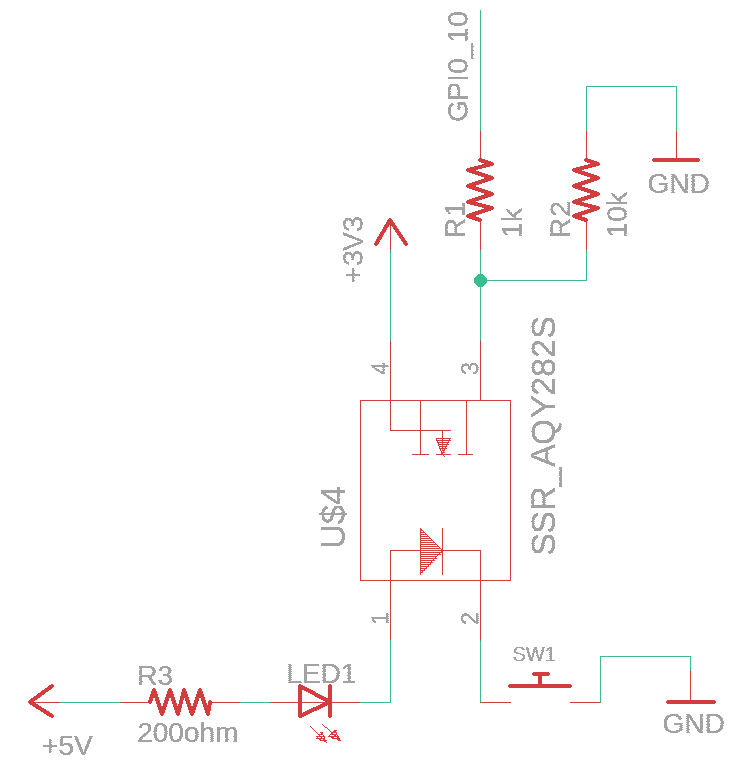
To get the most benefit from this, the +5V supply should be completely isolated from the 3.3v.
Also, it would be best to add a diode eg. 1N4148 inverse across the series opto+LED combination to prevent possible reverse breakdown from transients. Depending on the forward voltage of the LED you might not have much voltage left for the 200 ohm resistor so the current might not be well controlled (with consequences for the SSR operation, over time and temperature). Consider putting them in parallel, each with a series resistor.
Also, your SSR should function fine at the output stage, but it may be very slow because of the relatively large MOSFETs used at relatively low current. The SSR ton toff will be slow anyway because of the photovoltaic coupling but you'll also have a slow rise and fall time. You'll be debouncing it anyway, so it probably doesn't matter at all, but it would be a bit better if you had a Schmitt trigger input. I don't think R1 is doing anything of value- if the optocoupler fails the connection 3.3V will probably kill everything connected to that power rail anyway (assuming a high enough voltage and a return path).
Edit: R1 does prevent excessive current if a GPIO is set to output accidentally.

