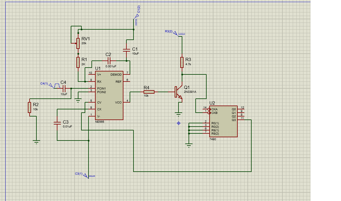
I just learned the working of NE565 and I tried to simulate a Frequency as multiplier using 565 in Proteus , but I don't know why PIN 4 of my NE565 is not giving any output . Its coming plane blank in output waveform in the oscilloscope . Please can someone help me in getting to know where I have gone wrong ?
I have attached my circuit diagram with my post.
Can someone help me in getting to know what is wrong with my Frequency multiplier circuit using 565?
\$\begingroup\$
\$\endgroup\$
4
-
2\$\begingroup\$ The NE565 is a PLL IC, PLLs aren't the easiest to simulate. What I would do is first try to get the NE565 working on its own, stick to the typical application diagram as shown in the datasheet and try to get that working. I would copy this schematic and remove Q1 and U2. Connect pin 4 and 5 of the NE565 directly. If needed adjust the value of C3 and/or the reference clock frequency. When that works, add Q1 and U2 but leave pins 4 and 5 as is. Just frequency divide the signal from pin 4 and see if that works. If it does then connect pin 5 to U2 and adjust C3 and/or the reference clock frequency \$\endgroup\$– BimpelrekkieCommented Oct 9, 2019 at 7:09
-
\$\begingroup\$ I am sorry but I am still not getting anything on PIN 4. Is there any possibility that this may be due to a bug in NE565 module in proteus ? Can you please recommend me any proper working circuit for 565 so that I can test it ? \$\endgroup\$– ferty567Commented Oct 9, 2019 at 9:53
-
\$\begingroup\$ Anything is possible, I didn't make the NE565 model so I don't know if/how it works. Is the VCO oscillating? If not maybe it needs a "kick" to startup. I usually use a pulsed current source for that, configure it such that it produces one current pulse shortly after the start of the simulation. \$\endgroup\$– BimpelrekkieCommented Oct 9, 2019 at 9:59
-
\$\begingroup\$ the 565 has an internal analog-multiplier as the phase-detector. Is that properly biased? \$\endgroup\$– analogsystemsrfCommented Oct 9, 2019 at 10:38
Add a comment
|
