3
\$\begingroup\$

I have been trying to simulate a fully controlled full bridge using SiC MOSFETs and so far haven't gettng at least expected results. So I tried to check what is happening using a single MOSFET and a simple circuit like this - Simple MOSFET driving circuit
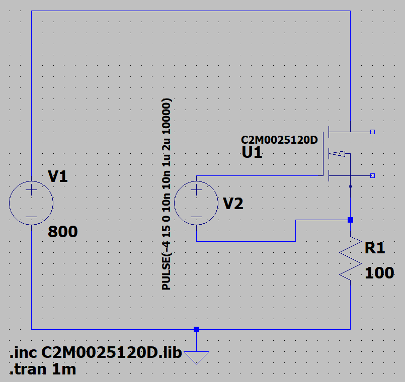
However, when I run the simulation, the current through the resistor looks like this -

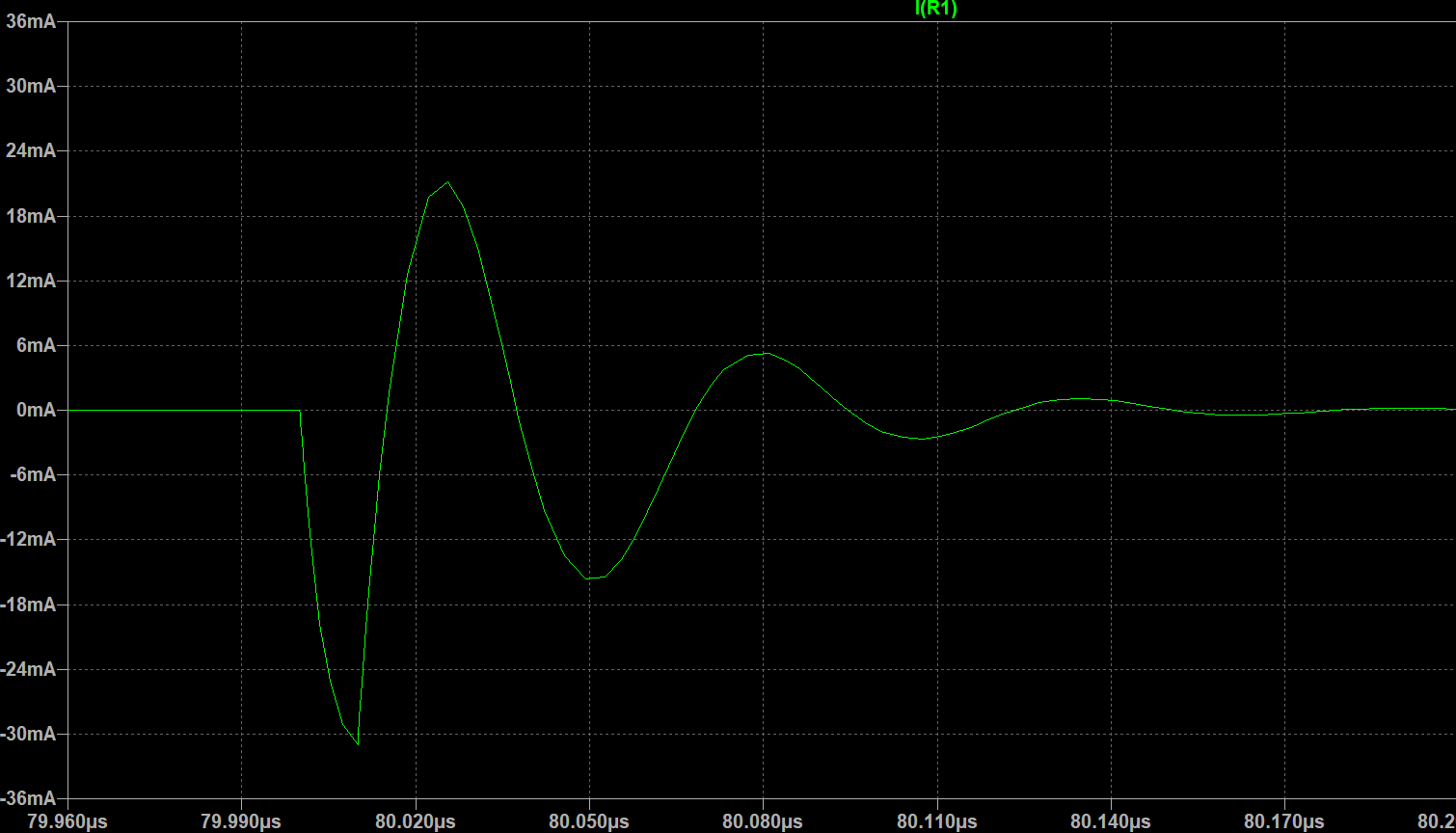
Current through MOSFET/resistor

I need to uderstand what I am doing wrong while simulating this circuit.
1. Does the gate need a resistor in series ?
2. The floating terminals of the MOSFET are Tj and Tc (temperatures) I have assumed that they can be kept floating.

Update-
Zoomed in waveform - zoomed waveform of one apparent pulse Edit -
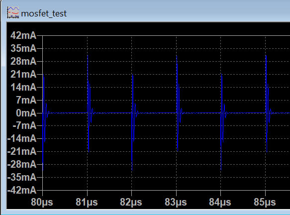
The MOSFET is rated at 1200V and 90A. The simulation works fine up until Vds as ~55V. Thereafter it breaks down and shows these similar results for any voltage above ~55V

\$\endgroup\$
7
  • 1
    \$\begingroup\$ zoom in on one of those switching events--- use 1` nanosecond/division \$\endgroup\$ Commented Oct 13, 2019 at 21:06
  • \$\begingroup\$ @analogsystemsrf updated the question \$\endgroup\$
    – shysd
    Commented Oct 16, 2019 at 11:48
  • \$\begingroup\$ I've had a similar experience trying to solve this problem recently and had to stop before i found a solution so i'd be interested in the result of this question too. \$\endgroup\$
    – hooskworks
    Commented Oct 16, 2019 at 11:50
  • \$\begingroup\$ Could you post the contents of the library? Only for this device. While I'm not saying this is the case, it could be that the model is not that good, or that it needs special SPICE considerations. \$\endgroup\$ Commented Oct 16, 2019 at 18:32
  • \$\begingroup\$ @aconcernedcitizen I downloaded the model from Wolfspeed/CREE's website and I'm skeptical about it being shared here because it required user signup. The website is go.wolfspeed.com \$\endgroup\$
    – shysd
    Commented Oct 17, 2019 at 15:42

1 Answer 1

4
\$\begingroup\$

The reason it is not giving the results you're expecting is because of your second assumption.

  1. The floating terminals of the MOSFET are Tj and Tc (temperatures) I have assumed that they can be kept floating.

The Cree C2M SiC MOSFET PSPICE MODEL Quick start guide REV 1.8 (which was available when I downloading all of the spice models in one zip-file some time ago) specifies the following

The Junction Temperature terminal (Tj) can either be used to read junction temperature or to fix junction temperature. This terminal can be left floating.

The Case Temperature terminal (Tc) must be connected to either a voltage source or a Heat Sink RC Network. This terminal should not be left floating.

The reason is that the electrical and thermal circuits of the model are connected through the device equations. This is true for most SPICE models of semiconductors.

I connected a dc voltage source to the Tc terminal and managed to successfully simulate your circuit in LTSpice IV.

Note: Due to the discontinuities in the models from Cree/Wolfspeed (and others), it is often necessary to modify the simulation tolerances to get the simulation to converge.

\$\endgroup\$
2
  • \$\begingroup\$ Thanks! It seems like it is super easy to miss. Answer accpeted. \$\endgroup\$
    – shysd
    Commented Nov 29, 2019 at 9:02
  • \$\begingroup\$ @hooksworks In case you have missed it \$\endgroup\$
    – shysd
    Commented Dec 1, 2019 at 7:18

Your Answer

By clicking “Post Your Answer”, you agree to our terms of service and acknowledge you have read our privacy policy.

Not the answer you're looking for? Browse other questions tagged or ask your own question.