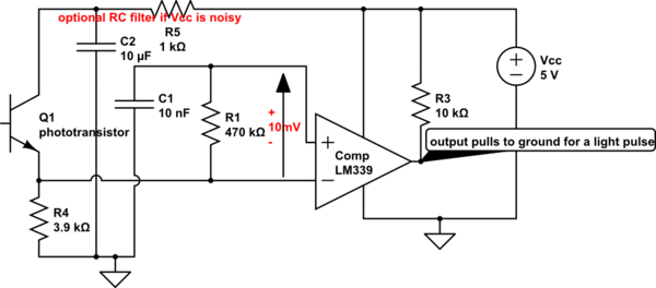
The LM339 is a comparator that has a somewhat unique characteristic: it uses a PNP input stage that has nearly constant 25nA bias current. This design idea takes advantage of LM339 bias current to generate a DC offset via R1. Have never tried this idea before...its a design-by-specsheet.
R1=470k gives an offset voltage of about 10mV. This offset is about twice the inherent +/- 5mV offset of the comparator itself. That's not much noise immunity, but may be sufficient. You can increase offset by raising R1 value - sensitivity to light pulses will be poorer. This circuit may be prone to oscillation with a poor layout (I'd expect trouble on a breadboard).
C1 can be changed to accept pulses of different durations. C1=500pf is about appropriate for IR pulses of 50 microseconds. A really sensitive phototransistor may saturate in daylight and not detect light pulses...if so, R4 must be reduced in value.
Note that comparator output idles at logic "high", and pulses to logic "low" when the photo-transistor sees a pulse.

simulate this circuit – Schematic created using CircuitLab
Edit:
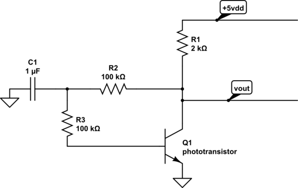
Another simpler version. R1 again creates about 10mV offset by means of LM339 input current. C1 (below) creates an average reference voltage proportional to ambient light hitting the phototransistor.
An RC filter (C2,R5) is added to the DC supply voltage in an effort to keep supply noise from triggering an output.
A pulse of light pulls the comparator output down from +5V to ground. The RC time-constant (R1*C1) determines sensitivity to ambient light changes. Decrease R4 to decrease sensitivity to light pulses:

simulate this circuit


