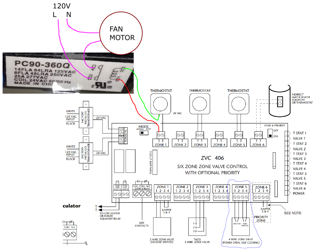
The diagram below shows the control circuitry of a heating system. I am trying to understand why the wiring depicted here caused the fan relay (PC90-360Q) to 'chatter' constantly when powered on.
Like many HVAC systems the controls operate on a 24 VAC signal which is produced by a transformer stepping down from 120V. Various equipment such as pumps & fans run on 120V also and so relays are used to mediate between the controls & the devices.
The seemingly relevant part of the intended operation was as follows:
- System is powered on
- Thermostat detects heat is needed; closes its internal switch
- Red / green path is energized through the fan relay coil
- Water pump relay is also energized (via one of the zone sections on the bottom, all actually wired as in the blue example)
- Fan relay closes its 120V contacts, energizing fan motor
Now what actually happened was that when the thermostat switch would close, the fan relay would 'chatter' seeming to switch on/off fairly rapidly.
The problem was not the thermostat itself - replacing it with a jumper wire produced the same result.
Notes:
The control voltage was actually about 26VAC, but that seems to be within tolerance as far as I am aware.
The controller ZVC406 is a self-contained board which normally just operates thermostats, valves, & pumps. Controlling the fan was an additional requirement necessitating the addition of the relay in question.
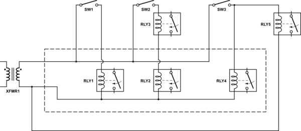
FYI I have actually solved the issue by instead wiring the relay between the switched output of the thermostat and the return pole of the transformer (i.e. a parallel path instead of series). So this question is really just for my own understanding.


