1
\$\begingroup\$

I need control sewing machine speed and needle position over arduino project.

  • Current sewing machine is: Brother X5, with 70 Watt motor with foot pedal control.

Speed of motor will controlling by triac dimmer (image attached) but want to change dimmer resistance (rheostat) throw arduino, progragrammatically. Not with servo motor.
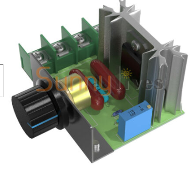
enter image description here

Q1: How can I change resistor resistance to form arduino programmatically?

Q2: Can I control motor speed sending 220V AC as pulses? (without triac dimmer)

For needle position plan to use magnet sensor. "Reed Switch Magnetic Sensor" Or "Hall Sensor" Problem is vibration of machine and spinning speed is factors,

Q3: Which sensor best suit in this case?

\$\endgroup\$
9
  • 1
    \$\begingroup\$ Q2: The most common type of AC motor, an induction motor, cannot be controlled this way since voltage and frequency affects speed (not only does the 220AC from the wall affect how fast it turns, but so does the 50/60Hz.). To control its speed you have to basically make a custom sine-wave which is very, very involved. You cannot speed control induction motors like a DC brushed motors. But I don't know what type of motor is used in a sewing machine. \$\endgroup\$
    – DKNguyen
    Commented Nov 1, 2019 at 20:57
  • \$\begingroup\$ Sewing machines are traditionally brushed motors offering speed control right down to 0. That kind of speed control is probably rather dangerous to hack : it probably isn't isolated from mains. The Arduino won't like that... \$\endgroup\$
    – user16324
    Commented Nov 1, 2019 at 22:04
  • 1
    \$\begingroup\$ @DKNguyen home-grade sewing machines use brushed universal motors, not induction motors (as industrials may use) and triac control is indeed the successor to the original rheostats. Fancier ones probably have servoed brushless motors. \$\endgroup\$ Commented Nov 2, 2019 at 1:34
  • 1
    \$\begingroup\$ There's really no easy, safe way to do triac control from an Arduino. A finished appliance would possibly float the MCU at mains voltage (while isolating it from the user) but that grossly complicates debugging and is just plain not acceptable for a hobby project. Otherwise you need an opto-coupler on the zero crossing detector, and probably an opto-triac to drive the power triac. And of course an isolated supply to power the MCU. In terms of realistic advice, the extreme degree of interaction with the mains means you should drop this project and pick something else to work on instead. \$\endgroup\$ Commented Nov 2, 2019 at 1:39
  • \$\begingroup\$ @ChrisStratton Thanks you for detailed comment. In worst case I will use triac dimmer with manual rheostat,it means fixed motor speed, but needle position will controled. Like this project: youtube.com/watch?v=yFy6KSMqnZM&t=576 But I wanna project like this (without Embroidery) but speed controlled by programmatically. What is your opinion about use PWM instead of triac dimmer? \$\endgroup\$ Commented Nov 2, 2019 at 8:13

1 Answer 1

1
\$\begingroup\$

If the machine has a brushed or universal motor, you can use a triac dimmer to control its speed.

However, triac dimmers are annoying to control. They fire on each mains cycle, ie every 10ms on 50Hz mains which inserts a large phase lag in the control loop. Also the input-output curve is very nonlinear.

If you want to control needle position you will need fast and accurate control, so you don't want to insert a large phase lag in your control loop. You'd need a smart control algorithm to compensate for this lag.

A much better scheme is to rectify mains and smooth it with a capacitor, then use high-ish frequency PWM like 10-20 kHz through a MOSFET. This has much lower phase lag, and would be easier to control. You can also control current through the motor, if you want to control torque.

For example, I have several electric drills. Most drills use triac dimmers. When using such a drill to drive a screw it is impossible to control torque and speed accurately, and the screw always ends up either deep into the workpiece, or sticking out. Triac dimmers just aren't accurate. I have another mains powered drill which uses a rectifier and PWM dimmer, and this one is very easy to control, the screw ends up perfectly flush with the workpiece every time.

Note your project uses high voltage thus it will be dangerous. Be careful.

\$\endgroup\$
2
  • \$\begingroup\$ About "PWM like 10-20 kHz through a MOSFET" bit more question. As I know this only possible on DC. Can I use PWM for 220V AC? As @chris-stratton said, domestic sewing machine motor is universal motor, and this mean it will work with DC aslo, but how many volt DC I need? About tagin needle position, in youtube some peaple use proximity sensor and it work fine.This project in low RPM, and for me also this kind of RPM is ok. Link: youtube.com/watch?v=yFy6KSMqnZM&t=576 I also need like this video (without Embroidery) but motor speed controlled throug Arduino. \$\endgroup\$ Commented Nov 2, 2019 at 8:01
  • \$\begingroup\$ The guy in this video uses a triac dimmer to set motor speed, and a static relay to turn the motor on/off. This will work at slow rpm. \$\endgroup\$
    – bobflux
    Commented Nov 2, 2019 at 22:26

Your Answer

By clicking “Post Your Answer”, you agree to our terms of service and acknowledge you have read our privacy policy.

Not the answer you're looking for? Browse other questions tagged or ask your own question.