2
\$\begingroup\$

My apologies if this isn't the most appropriate forum to ask this question, but I have found the response from users on this form to be extremely helpful in the past with my electrical questions.

I am new to impedance balancing so bear with me. I have a transmitter and receiver with 2000 meters of electrical cable connecting the two. The signal I am transmitting is a 3.3 volt digital signal. I am trying to impedance balance this network and a bit confused where to hook up my VNA. I drew a diagram below, is this correct? If I understand it, my VNA connects to the transmitter circuit while it is connected to the 2000 m transmission cable, which is then connected to the receiving circuit. Using my VNA and a Smith Chart, I will impedance balance the TX circuit with some "L" network including a certain value inductor and capacitor. After that is balanced on the VNA, I connect my VNA at the receiving end and do the same type of impedance balance.

Does this make sense or am I going about this wrong? Thanks for any input anyone has.

enter image description here enter image description here

\$\endgroup\$
9
  • \$\begingroup\$ Is your 3.3V signal even going to make it that far? There doesn't seem to be anything indicating anything particularly special about it such as having isolation or being differential. If the signal is only one-way though, you only need to terminate one end (the receiver for parallel termination, or the transmitter for series termination). Not sure why your components are placed the way they are. The line already has parasitic components in those positions. Your job is to make it appear to go on forever, not just make more of the same which still ends abruptly at your receiver. \$\endgroup\$
    – DKNguyen
    Commented Nov 1, 2019 at 21:45
  • \$\begingroup\$ Post the datasheet for the cable, it might have an attenuation factor. \$\endgroup\$
    – Voltage Spike
    Commented Nov 1, 2019 at 21:52
  • \$\begingroup\$ What is the switching frequency of the digital signal? \$\endgroup\$
    – remcycles
    Commented Nov 1, 2019 at 22:25
  • 1
    \$\begingroup\$ Question: why do you want to "match" the transmission line? By the the pictures one can tell that your actual goal is mostlikely to transmit data via UART over long distance. Many ppl already dealt with this kind of problem. There is a reason why standards like RS485 exists. \$\endgroup\$ Commented Nov 6, 2019 at 16:14
  • \$\begingroup\$ @ChristianB. Good point. I'm assuming that the OP is coming from an amateur radio background and not industrial. A quick check shows RS485 is designed for a max of 1,200 meters. If I were to recommend an alternative, I'd look into 4-20mA current loops. en.wikipedia.org/wiki/Current_loop#Long_circuits \$\endgroup\$
    – remcycles
    Commented Nov 6, 2019 at 17:56

4 Answers 4

4
\$\begingroup\$

I'd be worried about attenuation in a cable that long, but I suppose it depends on the switching frequency of your digital signal. The edges of the digital signal will be slowed at the receiving end due to the capacitance of the cable. You can measure that capacitance with your VNA, but for the most part I'd tackle this in the time domain. The VNA won't help with analyzing at DC. If your digital signal toggles slowly enough the RF attenuation won't matter, but the cable resistance and capacitance will be significant. A quick check on a resistance calculator for 20AWG (used in RG-58) shows ~66 ohms. I'm not sure what the shield resistance would be, but you should measure it.

Since a digital square wave has many frequency components, a lumped LC network like you show won't be a good choice, since that would match well at only one frequency.

You need to match both the source and load impedance to the characteristic impedance of the transmission line, most likely 50 ohms, over the intended frequency to prevent reflections. Your digital TX should go through a bus driver to ensure a low source impedance to charge the cable capacitance quickly and lower the rise and fall times for the transitions. A 50 ohm series resistor would be a sufficient wide-bandwidth match for an ideal low impedance source. Your RX is probably a very high impedance, so a 50 ohm shunt resistor in parallel with the RX should suffice.

Assuming a zero impedance source at TX and infinite load impedance at RX, and factoring in the example cable resistance and the 50 termination resistors, the TX will see an impedance of 50+66+50+10=176 ohms (TX -> 50 ohm -> 66 ohm center conductor -> RX pin -> 50 ohm -> 10 ohm coax shield -> TX GND) and it will drive 3.3V/176ohm=18.75mA. The RX end will only see 18.75mA/50ohm=0.94V across the load termination resistor once the TX voltage settles to logic high. You can bring that back up to 3.3V with a comparator (with hysteresis, aka Schmitt trigger) before the RX pin.

This page has more information about terminating digital signals on transmission lines: https://www.marvintest.com/KnowledgeBase/KBArticle.aspx?ID=196

A similar question was asked recently, and you might find the information there helpful: 1 kHz clock over long wire

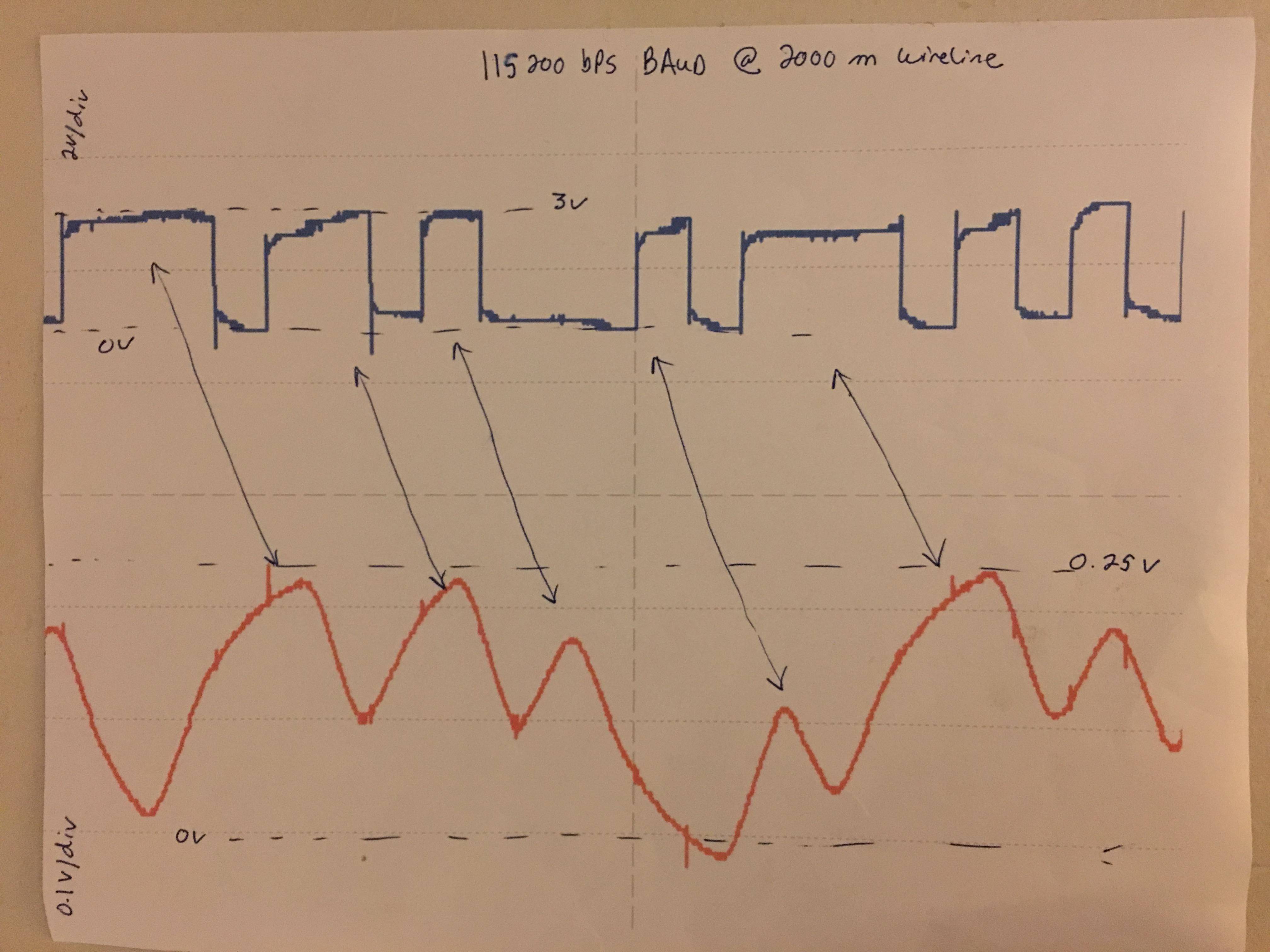
Update: Looking at your first oscilloscope plot, you can see the received signal has the distinct look of a capacitor charging and discharging. The signal is being low-pass filtered by the source impedance of the TX and the capacitance of the cable. A bus driver at the TX will help ensure faster transitions by lowering the source impedance, which is the R in the RC time constant of this system.

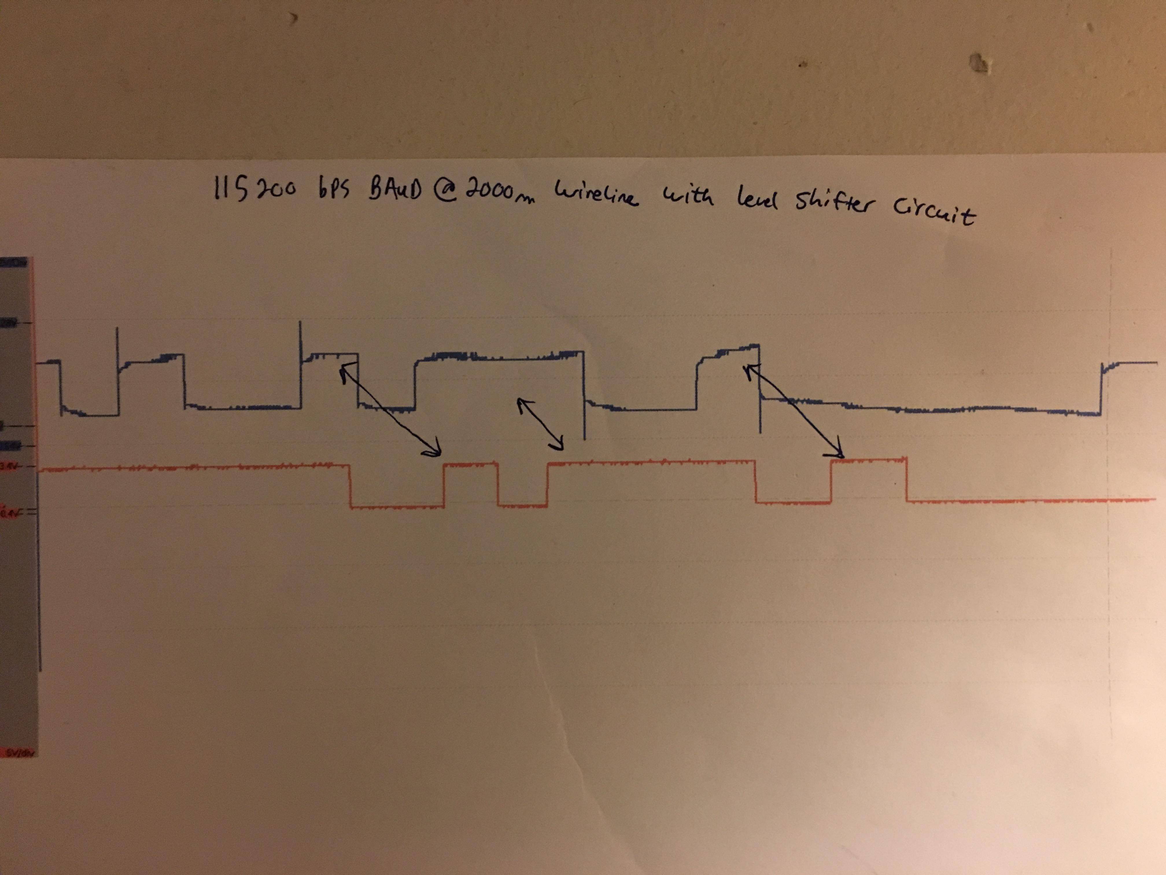
You can also see that the average value of the signal rises and falls over time depending on the changing duty cycle of of the TX signal. This causes problems for the digital logic input of the RX pin. If the TX sends mostly ones, there won't be enough time for the received signal voltage to drop below the logic low threshold when it sends a zero, and you'll just see all ones. That is why your second plot has failed to notice some transitions. One way to tackle this problem is to use a comparator circuit with hysteresis to set to logic thresholds that work better for your TX and cable setup.

Update: Measuring the characteristic impedance of this unknown transmission line is only needed for determining the proper termination resistors. Note that it takes a little while to learn how to operate, read, and understand results from a VNA. You must also calibrate the VNA for the test cables you connect to the device you are measuring (in this case the device is a piece of your transmission line).

These two documents explain how to measure the characteristic impedance of a transmission line.

Section 5.9, PDF page 113, of: https://literature.cdn.keysight.com/litweb/pdf/5950-3000.pdf

And: https://www.ietlabs.com/pdf/application_notes/5-Characteristic%20Cable%20Impedance-Digibridge.pdf

The basic idea is to make two measurements of a short length of cable, one with the far end of the cable "open" (shield and center conductor not connected to each other or anything else), and the other with the far end "shorted" (shield and center conductor connected or soldered together). It doesn't have the full length of cable that you are using. A few feet should suffice.

When you have the impedance measurements from the open and short, \$|Z_{open}|\$ and \$|Z_{short}|\$, you can calculate the characteristic impedance (\$|Z_{0}|\$) with:

\$|Z_{0}|=\sqrt{|Z_{open}|*|Z_{short}|}\$

\$\endgroup\$
9
  • \$\begingroup\$ Wow thank you for the very detailed help. I already have this transmitting and receiving okay at 56,000 bps. When I turn it up to 115200 bps, the digital signal is not decipherable. Like you said, the rise and fall times lag and then it has a compounding effect and it turns into a mess. The resistance of my transmission cable is 22 ohms. If that’s the case, impedance matching is as simple as a 22 ohm series resister at transmitter end and 22 ohm shunt resister at receiver end? Both the transmitter and receiver are just raspberry pi computers. Thanks again for your help. \$\endgroup\$
    – Dustin
    Commented Nov 3, 2019 at 20:46
  • 1
    \$\begingroup\$ I also just added two images of the signal from my oscilloscope. The first image shows the blue signal which is at the transmitting end. The red signal is at the receiving end. You can see how it has been distorted. The second image shows the same measurements, except the red signal is also at the receiving end but after running it through a level shifter circuit to help clean the signal up. It does a pretty good job, but you can see the clock time is out and in some cases, “offs” are merged with “ons”. Hope that makes sense . I thought impedance balancing this would be a good start \$\endgroup\$
    – Dustin
    Commented Nov 3, 2019 at 21:04
  • \$\begingroup\$ That 22 ohms is the DC resistance of the transmission line from one end to the other, right? What type of transmission line is it? Twisted pair, or coax? I had assumed coax, but twisted pair is more likely. \$\endgroup\$
    – remcycles
    Commented Nov 6, 2019 at 17:58
  • \$\begingroup\$ The values of the matching resistors need to match the characteristic impedance of the transmission line, which is independent of the DC resistance. It depends on the dimensions and materials of the transmission line which determine the capacitance and inductance per unit length. \$\endgroup\$
    – remcycles
    Commented Nov 6, 2019 at 18:00
  • 1
    \$\begingroup\$ For the problem of the average DC component of the received signal rising and falling over time, one approach is to switch to a DC-balanced encoding -- see e.g. the Manchester and 8b/10b encodings. \$\endgroup\$ Commented Nov 7, 2019 at 20:11
1
\$\begingroup\$

You can't just connect your VNA to the circuit as you have drawn. Doing so will change the behavior of the network you are trying to measure.

You can still do what you want though. Just disconnect the transmission line from the transmitter and connect your VNA to the transmitter at this point. Do a one port reflection measurement of the transmitter, and from this design your matching network. You can then do another measurement to confirm the match. This is then repeated for the receiver. Disconnect transmission line, connect VNA, measure reflection, design matching network, verify network.

Now each side is matched. You can connect your transmission line back in and everything should work.

Depending on the frequency of operation and the type of transmission lines you are working with connecting and disconnecting these things may not be trivial. If you aren't careful you can introduce error in your measurement.

\$\endgroup\$
0
0
\$\begingroup\$

Another way to solve this problem is a 4-20mA loop, which will drive the signals as currents instead of voltages (4mA or 20mA for a zero or a one). It will make dealing with the resistive cable loss over this long distance much easier, and will be more immune to noise picked up by the cable acting as an antenna.

A pair of boards like these can help convert your 3.3V digital signal to a 4-20mA signal and back.

For the TX side: https://www.amazon.com/KNACRO-Voltage-Current-Conversion-current/dp/B0793KZDWT

For the RX side: https://www.amazon.com/DROK-Current-Voltage-Converter-Transmitter/dp/B073PRCDY2

\$\endgroup\$
0
\$\begingroup\$

Thanks everyone for your comments. I ended up getting it to work by using a 74HC14 Hex Schmitt Trigger. No impedance balancing necessary, just needed to clean the signal up with this chip. Its not perfect yet but for the most part data is transferring and I can work on perfecting the system.

\$\endgroup\$

Your Answer

By clicking “Post Your Answer”, you agree to our terms of service and acknowledge you have read our privacy policy.

Not the answer you're looking for? Browse other questions tagged or ask your own question.