1
\$\begingroup\$

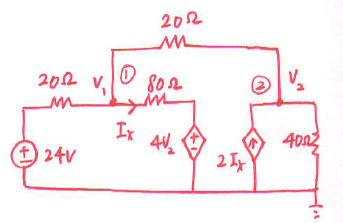
I am presented with the circuit shown in the figure below. enter image description here
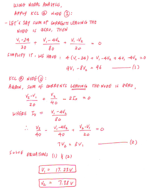
The hand calculations are as follows: enter image description here
When I build the circuit in Multisim as shown in the image below: enter image description here
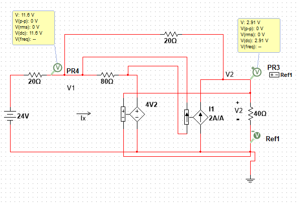
My calculations are not matching up with the simulation results. Im pretty confident in my hand calculations. It is the simulation I am not sure about, but I could be wrong. Can anyone see what I did wrong?

\$\endgroup\$
5
  • 1
    \$\begingroup\$ In the multi sim model, the input to the cccs is shorting the 80 ohm resistor. \$\endgroup\$
    – The Photon
    Commented Nov 2, 2019 at 19:10
  • \$\begingroup\$ Im not sure exactly how to correct that. \$\endgroup\$ Commented Nov 2, 2019 at 19:13
  • 1
    \$\begingroup\$ Put the control port of the cccs in series with the resistor instead of in parallel. \$\endgroup\$
    – The Photon
    Commented Nov 2, 2019 at 19:15
  • \$\begingroup\$ Thank you, that worked. I would like to show the snapshot of the corrected version, should I add that as an edit to my original post? \$\endgroup\$ Commented Nov 2, 2019 at 19:19
  • \$\begingroup\$ You could post an answer and include it there. \$\endgroup\$
    – The Photon
    Commented Nov 2, 2019 at 19:20

1 Answer 1

1
\$\begingroup\$

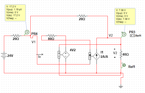
As The Photon suggested in his comment earlier, I was shorting out the CCCS with the 80 Ohm resistor. Below is the diagram that shows the 80 Ohm Resistor connected in series with the CCCS instead of in parallel. enter image description here

\$\endgroup\$

Your Answer

By clicking “Post Your Answer”, you agree to our terms of service and acknowledge you have read our privacy policy.

Not the answer you're looking for? Browse other questions tagged or ask your own question.