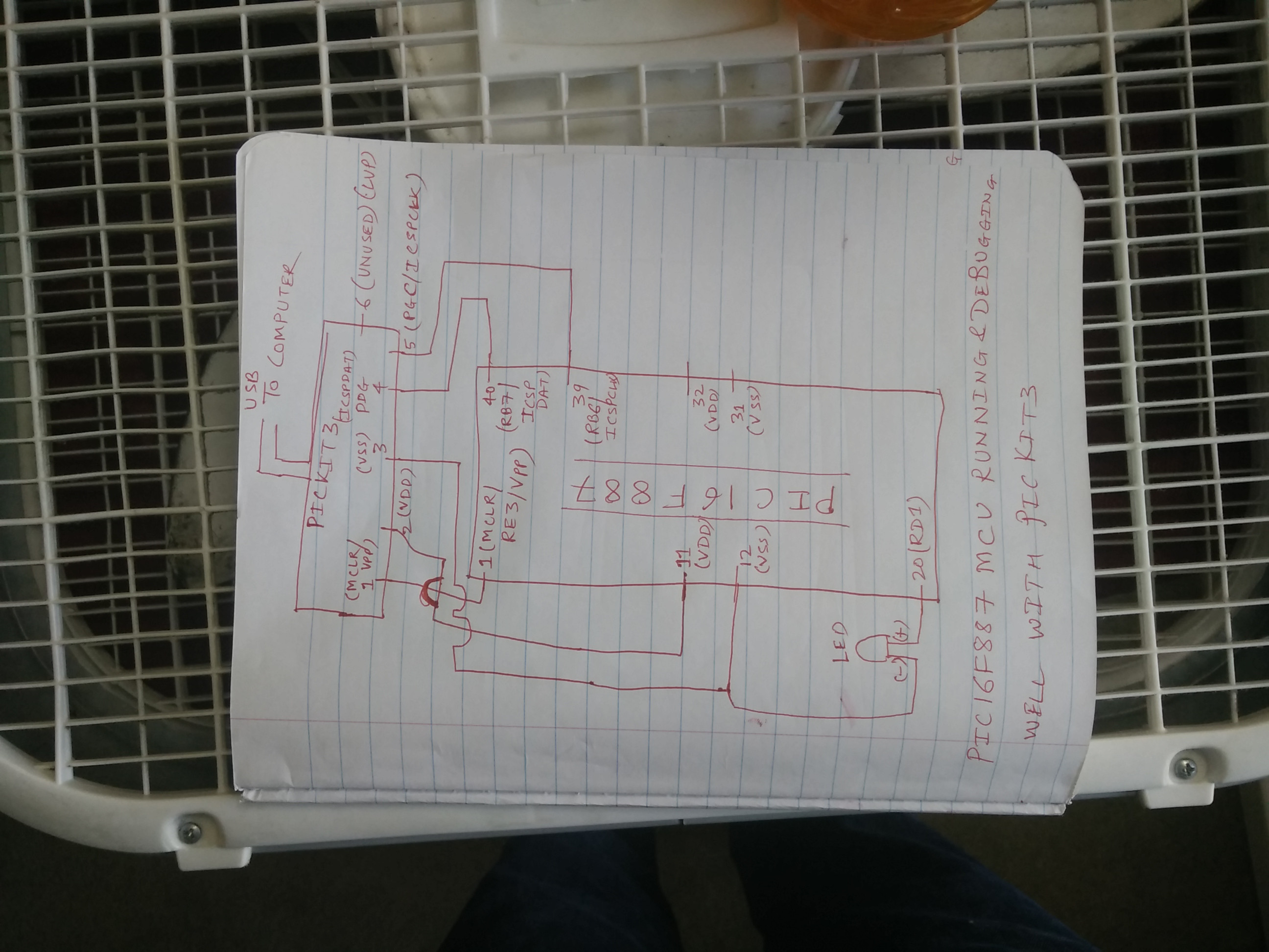
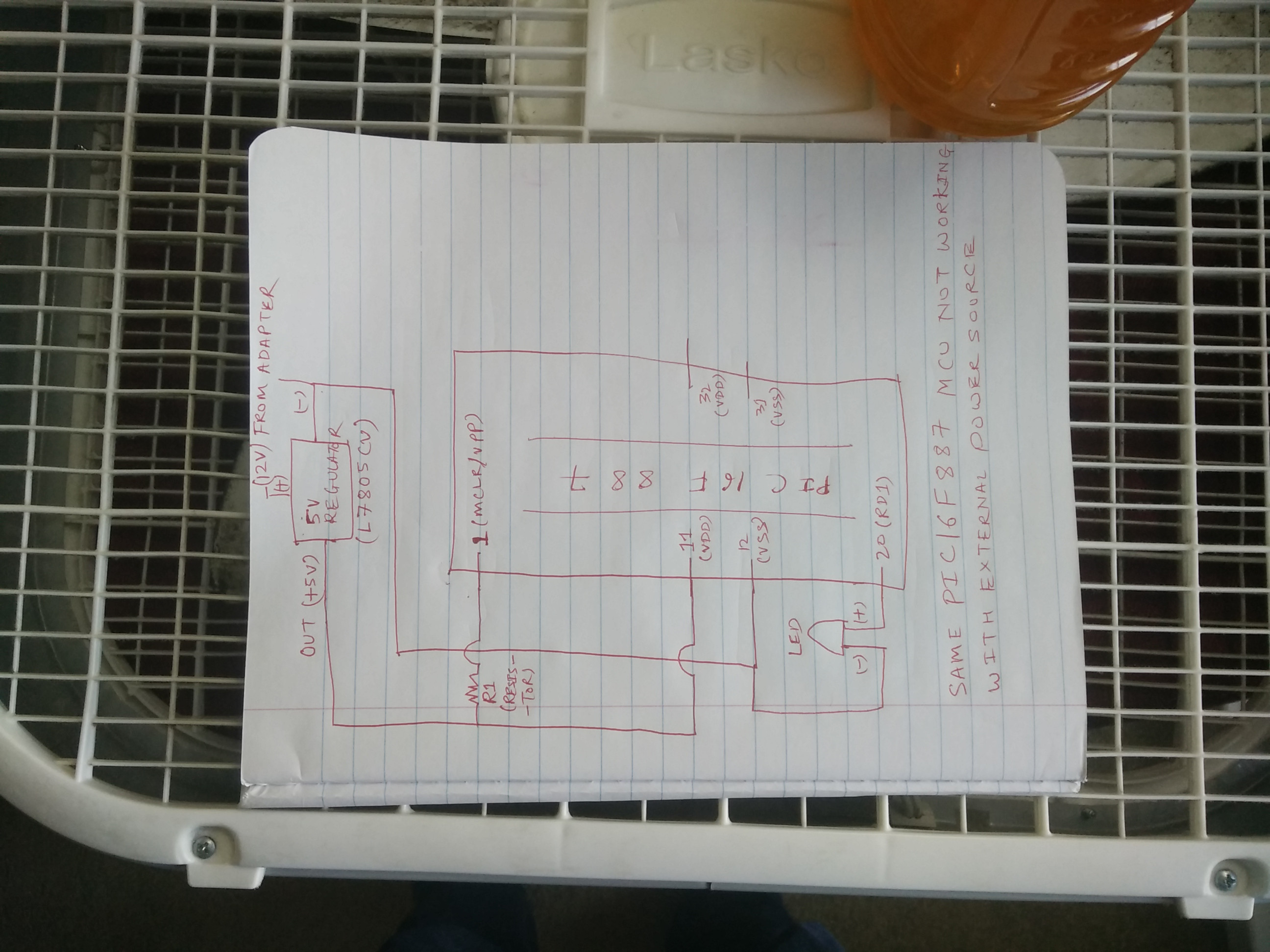
I am a newbie with PIC doing my first project to understand how PICs work. I have some experience with Arduino and trying to learn PIC now.
I have chosen PIC16F887 (40 pin DIP package) as my first PIC chip. I am using MPLAB v5.30. I am only trying to blink an LED attached to pin 20 (RD1) in my first project. But what I am experiencing is that the PIC BOTH Runs and Debugs well when its connected to PICKIT3, but when I am supplying the power through an external source, nothing happens at all.
While connected to PICKIT3, in order to run the project in "release mode", I am using the option "Program device for Production Main Project" from MPLAB. To debug, I am only running - "Debug Main Project" from the debug menu. Both these options end up with PIC running on the breadboard. I understand that with the external power source, the MCU is not supposed to work with a debug build. Hence before powering from external source, I am using the "Program device for Production Main Project" MPLAB option to program the chip. I also tried option - "Run Main Project", but this option does not work, neither with PICKIT3 connected nor with the external power. That seems strange.
For external supply I am using the L7805CV 5v voltage regulator. I am also pulling up the pin1-MCLR using the resistor "R1" when using external source. Have tried various values of R1 from 4800 ohms to 68000 ohms with no luck. I am attaching the hand drawn circuits here which I am using both with PICKIT3 and external power. My code which I am trying to run is also mentioned below. I have tried setting MCLRE as OFF, ON and default (not mentioning in code at all) with no luck. The crystal frequencies tried as 8, 20 and 32 mhz.
Can someone please see whats missing in the circuit or the code? Also notice that, this MCU has two VDD and VSS pins. Seems unlikely to me, but do I need to supply voltage to both of them in order for the chip to work? I have only one chip currently, do not want to fry it, hence have not tried this option.
// PIC16F887 Configuration Bit Settings

// 'C' source line config statements

// CONFIG1
#pragma config FOSC = INTRC_NOCLKOUT// Oscillator Selection bits (INTOSCIO oscillator: I/O function on RA6/OSC2/CLKOUT pin, I/O function on RA7/OSC1/CLKIN)
#pragma config WDTE = OFF       // Watchdog Timer Enable bit (WDT disabled and can be enabled by SWDTEN bit of the WDTCON register)
#pragma config PWRTE = OFF      // Power-up Timer Enable bit (PWRT disabled)
#pragma config MCLRE = ON      // RE3/MCLR pin function select bit (RE3/MCLR pin function is digital input, MCLR internally tied to VDD)
#pragma config CP = OFF         // Code Protection bit (Program memory code protection is disabled)
#pragma config CPD = OFF        // Data Code Protection bit (Data memory code protection is disabled)
#pragma config BOREN = OFF      // Brown Out Reset Selection bits (BOR disabled)
#pragma config IESO = OFF       // Internal External Switchover bit (Internal/External Switchover mode is disabled)
#pragma config FCMEN = ON       // Fail-Safe Clock Monitor Enabled bit (Fail-Safe Clock Monitor is enabled)
#pragma config LVP = ON         // Low Voltage Programming Enable bit (RB3/PGM pin has PGM function, low voltage programming enabled)

// CONFIG2
#pragma config BOR4V = BOR40V   // Brown-out Reset Selection bit (Brown-out Reset set to 4.0V)
#pragma config WRT = OFF        // Flash Program Memory Self Write Enable bits (Write protection off)

// #pragma config statements should precede project file includes.
// Use project enums instead of #define for ON and OFF.

#include <xc.h>
#include <stdio.h>
#include <stdlib.h>

# define _XTAL_FREQ 20000000

void main()
{
    TRISD1=0;

    while(1)
    {
        RD1 = 1;
       __delay_ms(1000);
       RD1 = 0;
        __delay_ms(1000);
    }
}


