Physics 101
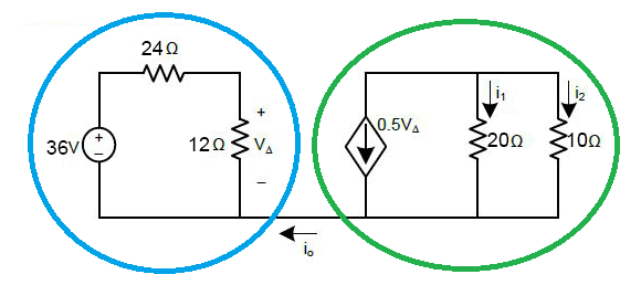
To get one thing immediately straight, imagine what would happen if there was a current along that wire connecting the blue circle of "matter in the universe" and the green circle of "matter in the universe?" (The assumption here is that \$i_0\$ is continuous and not a momentary "charge balancing" event.)

Not good stuff. A charge differential would build up between the two until -- no matter how far apart these two bits of matter were in the universe, even millions of light years apart -- there would be an arcing of charge to neutralize these two bits. And that assumes you had some way of nailing them down so they didn't move. More likely, they would vastly overwhelm any separating velocity or otherwise gravitational forces pulling them apart and would instead slam back towards each other with an impact that would shake the universe. (Maybe another "big bang?")
So you know without any thought at all, simply from basic physics and forget the electronics part, that these two separated "blobs" do not have anything other than \$i_0=0\:\text{A}\$. There's no other option, if you start with \$i_0\$ as continuous through all time and not a momentary event.
Electronics Analysis
That's one of your questions out of the way. So this means you can analyze these two circuits, separately, except that there is some "magic" in that something is measuring \$V_\Delta\$ in the blue-circled circuit and using that information to impel a current source magnitude in the other one. That doesn't violate common sense physics, so you can proceed.
The blue circled circuit on the left is a trivial voltage divider. So just compute, holding the bottom wire for now as the default "ground reference":
$$V_\Delta=+36\:\text{V}\cdot\frac{12\:\Omega}{12\:\Omega+24\:\Omega}= +12\:\text{V}$$
That confirms your own results I see near the bottom of your question.
The voltage-dependent current source in the green circled circuit on the right is then \$I=0.5\cdot V_\Delta=6\:\text{A}\$. As this value is positive and not negative, the computed current must point in the direction of the arrow given in the diagram, too.
I just want to make sure that you recognize that the the "0.5" you see
there has units of amps divided by volts, or Siemens. So the
equation is really either \$i=0.5\:\text{S}\cdot V_\Delta =6\:\text{A}\$ or else
\$i=\frac{V_\Delta}{2\:\Omega}=6\:\text{A}\$. Lesson here is never
forget dimensional analysis. This isn't mathematics 101. It's
physics/electronics 101. Mathematicians can treat all numbers as
unitless. A physicist or engineer doesn't have that freedom. Reality
IS and you always need to make sure that the units work out. It's a basic sanity test and, used properly and with wisdom, can be used to
guide you correctly in the right direction towards solutions you've
never dealt with before.
Now, in keeping with the idea that the bottom wire within the green circle is in fact tied to the bottom wire within the blue circle, where we treated that node as "ground", there is only one unknown voltage node in the green circle and we can use KCL for that node (call it \$v_x\$) and also add a few details regarding the resistors:
$$\begin{align*}\left(i_1=\frac{v_x}{20\:\Omega}\right)+\left(i_2=\frac{v_x}{10\:\Omega}\right)+\left(i=6\:\text{A}\right)&=0\:\text{A}\\\\\therefore\\\\v_x&=-40\:\text{V}\end{align*}$$
And from there I know the rest is trivial to work out. You already have your results, in fact.


