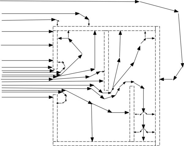
[ edited the diagram, to show TWO INTERNAL METALLIC BAFFLES that prevent a direct line-of-sight. ]
here is my thought on the Efield thru a hole in a Faraday Cage.
Why can we trust this diagram? Because the flux lines are also modeled ---exactly, in shape and in intensity --- by the current flows in a finite element grid; in such a grid, there may be attenuation BUT the currents into and out of a grid_element will not be zero. Very small currents are NOT zero currents, hence the interior of a Faraday Cage, with a HOLE,
is not ZERO current.

simulate this circuit – Schematic created using CircuitLab
What does this sketch tell us? Notice there are Efield flux lines everywhere into the cavity.
If the Efield changes, then the flux lines change and there will be currents (briefly) in the walls of the cavity. Should a circuit on a PCB also be within the cavity, then every point on your PCB will experience slight changes in currents (displacement currents).

