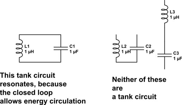
0
\$\begingroup\$

I understand that if a charged capacitor is placed with an inductor (and then remove the power supply,) the capacitor and inductor will exchange energy back and forth, it will basically oscillate and then slowly die out. Similarly, a resonance circuit (as I know RLC circuit with AC source) oscillates.

Then, what's the difference between these two circuits? Am I right thinking a resonance circuit sustains oscillation and a tank circuit oscillation dies out?

\$\endgroup\$
2
  • \$\begingroup\$ Prerna...an oscillator does not need an AC source. It creates sinusoidal signals "by itself". For this purpose, it needs an amplifier which compensates all the unavoidable losses within the circuit. Otherwise, the signal will die out... \$\endgroup\$
    – LvW
    Commented Nov 20, 2019 at 9:14
  • \$\begingroup\$ There is no difference; 2 names for the same beast. \$\endgroup\$
    – Andy aka
    Commented Nov 20, 2019 at 12:56

4 Answers 4

1
\$\begingroup\$

Am I right thinking a resonance circuit sustains oscillation and a tank circuit oscillation dies out

Both the ideal LC circuit and the oscillator tank (as you call it) are resonant circuits. A circuit is called in resonance if the frequency of the driving signal is same as the natural frequency of the circuit.
For an ideal LC circuit (shown below), the natural frequency is \$\omega_0 = \frac{1}{\sqrt{LC}}\$. If this circuit is driven with a current source at this frequency then the circuit will be in resonance. At resonance, the voltage across the capacitor (or inductor) is going to have infinite amplitude. This is because the impedance of the circuit between node A and B, given by \$\frac{1}{sC+\frac{1}{sL}}\$, is infinite.
Further, since there are no losses in the system the circuit can sustain oscillations at the natural frequency.
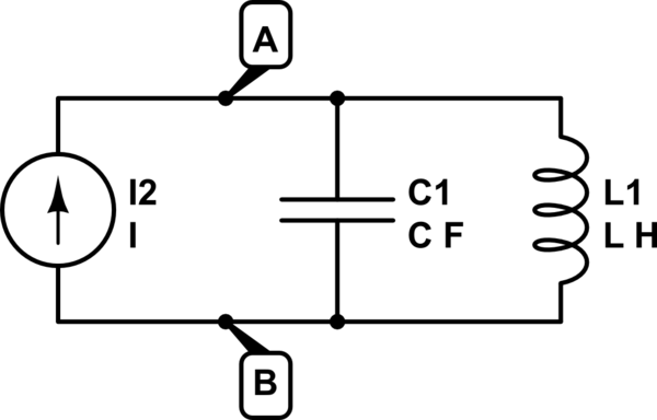
schematic

simulate this circuit – Schematic created using CircuitLab

Practically, there cannot be circuit with infinite impedance. And in reality, the inductors and capacitors have parasitic resistances which can be approximately modelled as a resistance parallel to the LC circuit close to the resonant frequency. This ensures that at the resonant frequency the impedance is finite (and equals \$R\$).
But the presence of the R implies losses inside the system and consequently this circuit will not sustain oscillations which will eventually die out.
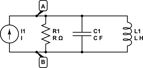
schematic

simulate this circuit

To compensate for these losses usually a non-linear active element is placed in parallel with the tank which would compensate for the losses inside the lossy LC tank (due to R).

what's the difference between these two circuits?

Both the circuits are parallel resonant LC circuits, ideal LC has no loss while oscillator tank has some loss.
Hopefully, it is clear. Let me know if not.

\$\endgroup\$
3
  • \$\begingroup\$ @sarthak....If a "non-linear active element is placed in parallel with the tank" it must be a negative resistance. This is the only solution. Alternatively, you must create a closed loop (feedback loop) consisting of the tank and an amplifier - and fulfill the oscillation condition (unity loop gain at the desired frequency) \$\endgroup\$
    – LvW
    Commented Nov 20, 2019 at 12:36
  • \$\begingroup\$ @LvW Yes it is indeed a negative resistance. Usually it is a cross coupled mos-pair. \$\endgroup\$
    – sarthak
    Commented Nov 20, 2019 at 15:05
  • \$\begingroup\$ However, it most cases it is more convenient to use filter structures with a positive feedback loop. \$\endgroup\$
    – LvW
    Commented Nov 20, 2019 at 15:17
0
\$\begingroup\$

An LC tank (consisting of an inductor and a capacitor in series) can be considered a resonant circuit, as you describe.

And yes, in an ideal world if you place a charged capacitor across an inductor they wil oscillate at their natural frequency forever. But in the real world there is resistive losses turning the electrical energy into heat, causing the oscillation to die out.

\$\endgroup\$
0
\$\begingroup\$

A resonant circuit will absorb/transform almost totally or in a large part the energy that he has or is being given. A LC tank and antennas are electromagnetic resonators, piezoelectric crystal suck as FBAR are electromechanical resonators. A system can be defined as an oscillator when it creates it's own signal. For instance Ring oscillators don't have any resonators.

\$\endgroup\$
0
\$\begingroup\$

in another interpretation

schematic

simulate this circuit – Schematic created using CircuitLab

\$\endgroup\$

Your Answer

By clicking “Post Your Answer”, you agree to our terms of service and acknowledge you have read our privacy policy.

Not the answer you're looking for? Browse other questions tagged or ask your own question.