0
\$\begingroup\$

Recently one of my mirocontrollers fried in a project on a perf board. Eight of the outputs are PWM, and aside from the power lines, there are no other outputs from the MCU. The PWM frequency is 40 kHz. All these output lines are routed to a connector with long, beefy solder tracks under the board. After going through the connector, each line meets a 2.2k resistor (series) and drives some transistor circuitry.

Two of the PWM channels worked on their own for quite a while before connecting the other six, so I first thought my troubles could be the result of continuous overcurrent. The MCU is rated for 200 mA max, but 5 V/2.2 kohms * eight channels only comes out to 18 mA.

I am inclined to say that the fast switching frequency combined with the beefy solder tracks pushed too much current in and out of the parasitic capacitance before the series resistors.

How much parasitic capacitance can lead solder introduce? I realize I could put the resistors closer to the MCU BEFORE the long tracks, but there is always a degree of parasitic capacitance in everything.

I would like to know if the following reasoning is correct:

If I solder a wire to a large copper ball (say apple-sized) and then plug the end of the wire onto my MCU PWM output pin, I will fry the unit as high current quickly rushes in and out of the ball's parasitic capacitance. If I did the same thing with just a bare wire, the capacitance would not be great enough to fry the controller. I have done several times in projects with no issues.

If the reasoning is correct (I would not like to test it :)) and all capacitors can draw huge momentary current, why does the ball fry the MCU and the wire doesn't?
Is there a calculation to help me understand this better?

\$\endgroup\$
5
  • 14
    \$\begingroup\$ No, you are mistaken. Whatever the actual issue is, it is not that \$\endgroup\$ Commented Nov 22, 2019 at 2:09
  • \$\begingroup\$ @Chris Stratton so my large solder tracks cannot fry a board? Is it possible that it was a faulty power supply? My scope shows my samsung USB block supply has a max votage of 5.6v at times... 6v is the absolut max voltage for my device... \$\endgroup\$
    – Hackstaar
    Commented Nov 22, 2019 at 2:12
  • 2
    \$\begingroup\$ Something else is wrong. It's generally bad ju ju to bring microcontroller port pins off-board without ESD protection, which is what you have described. If you put the resistors on the MCU side and perhaps add some protection TVS arrays to the pins you'll have a more bulletproof design. \$\endgroup\$ Commented Nov 22, 2019 at 2:46
  • \$\begingroup\$ the length of a trace or wire, presumed to be 50 ohms, and driven by 5 volts, requires 100 milliAmps until the trace/wire is charged up. The output FETs will be sized to handle the 100 milliAmps. \$\endgroup\$ Commented Nov 22, 2019 at 3:03
  • 1
    \$\begingroup\$ I agree with @SpehroPefhany that your sloppy layout is blowing the I/O pin drivers causing much excessive current, thus making for a very hot MCU. Remember these are CMOS devices and do NOT like surges or static of any kind. I did call it a sloppy layout as that is what you have built. Look at factory layouts and how clean they are, with surge protection for remote extensions close to the CPU/MCU. \$\endgroup\$
    – user105652
    Commented Nov 22, 2019 at 4:07

1 Answer 1

3
\$\begingroup\$

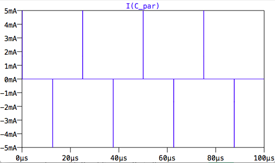
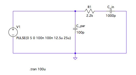
I also doubt parasitic capacitance is the issue here. I simulated a circuit with 100pF to ground (a huge amount) and a faux mosfet gate termination. and only saw ~5mA though it with rise/fall times of 100ns. If your rise times are much faster you will see more current, but according to this post:

How solder inductance affects RF circuits?

you'd be lucky to get significantly more than 1-5pF on the line.

Equivalent Circuit(?)

Huge cap on input for testing's sake.


~5mA spikes

Current through cap


Do you have schematics/pictures of the circuit? is it possible that you shorted two wires and that's why you draw so much current?

\$\endgroup\$

Your Answer

By clicking “Post Your Answer”, you agree to our terms of service and acknowledge you have read our privacy policy.

Not the answer you're looking for? Browse other questions tagged or ask your own question.