1
\$\begingroup\$

This is a follow up Question to What is use of R41 (base to emitter) resistor in Transistor Relay Circuit?

My doubt is can we connect the resistor R41 between emitter of optocouler and GND?

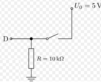
The pulldown resistor is usually connected to one end of a switch. enter image description here
and it would be more consistent to connect R41 (in original schematic) to the emitter of optocoupler (SWITCH).

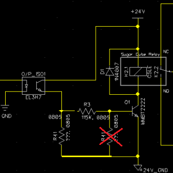
enter image description here

\$\endgroup\$
1
  • \$\begingroup\$ I think so too... \$\endgroup\$ Commented Jun 16, 2021 at 20:02

2 Answers 2

1
\$\begingroup\$

While it looks superficially like a voltage divider, the voltage on the base of the transitor is constrained to the range 0 to 1V by the transistor itself. The value for this part is usually such that only a very small current flows through it.

The purpose of R41 is to prevent any current that leaks through the opto-coupler or the transistor C-B junction from biasing the transisor partly on and causing it to overheat. 20uA leakage mutiplied by worst-case beta or 300 is 6mA, at about 24V that's 144mW of heat generated in the transistor.

\$\endgroup\$
0
\$\begingroup\$

The only reason I can think of for R41 to even exist is to add some threshold. R3 and R41 creates a voltage divider, the transistor won't turn on until the voltage over R41 exceeds ~0.6V.

Moving the resistor to the new location would remove the threshold. It could instead result in too little current flowing to the base.

Furthermore, there is no need for a pull-down resistor in this circuit. If the input to the base is floating, it won't conduct. If there is a long wire or a FET.

\$\endgroup\$

Your Answer

By clicking “Post Your Answer”, you agree to our terms of service and acknowledge you have read our privacy policy.

Not the answer you're looking for? Browse other questions tagged or ask your own question.