0
\$\begingroup\$

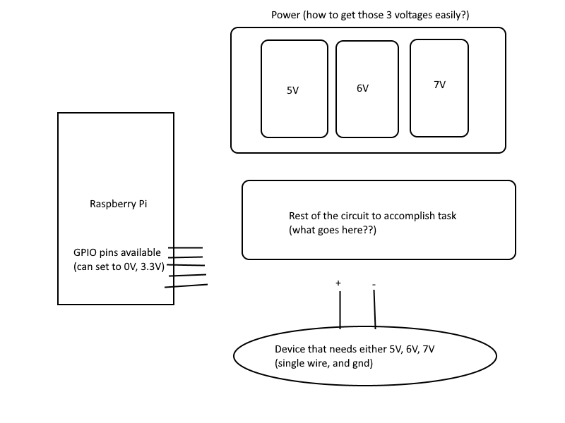
Here's my problem. I have a device to control that needs to always have one of three voltages applied to it: 5V, or 6V, or 7V. And I need to be able to programmatically switch between them.

What I have available is a general mirocontroller with GPIO pins that I can set at some different voltage (e.g. 3.3V). I have a feeling relay circuits could do this but I can't figure out how to switch between my 3 different voltages.

Question summary:

What circuit would implement this with simple components? How should I create the 3 voltages I need? Assume I can buy whatever simple parts from Amazon etc. enter image description here
\$\endgroup\$
4
  • \$\begingroup\$ Either (1) Use an eg LM317 regulator to produce each voltage - a resistor from ref to ground sets the voltage. Connecting the bottom end to ground with a transistor enable that reistor or (2) High side switchj transistor from each of 3 supplies. Each switched with a low side transistor driven by Pi. \$\endgroup\$
    – Russell McMahon
    Commented Nov 25, 2019 at 0:27
  • \$\begingroup\$ Does your RPi use a 5 VDC supply from which it creates an internal 3.3 V supply? Or... well, what does your "mains to DC" thing generate? Does it directly generate 3.3 V only? Or 5 V, with an internal regulator on the RPi to get down to 3.3 V? There may not be an entirely easy way to get 5 V, 6 V, and 7 V. Just pre-warning. Also, do you have any idea how much current is required by your multi-voltage device? \$\endgroup\$
    – jonk
    Commented Nov 25, 2019 at 0:28
  • 2
    \$\begingroup\$ How much current is drawn from these power rails? Are they used for power delivery, or simply to control some behavior? \$\endgroup\$
    – bitsmack
    Commented Nov 25, 2019 at 2:16
  • 1
    \$\begingroup\$ It's a sign of the times when a Raspberry Pi is described as a 'simple digital controller". \$\endgroup\$ Commented Nov 25, 2019 at 6:04

3 Answers 3

2
\$\begingroup\$

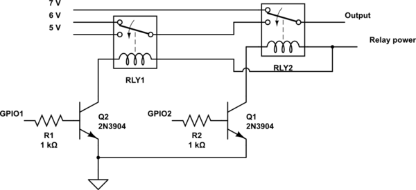
Two SPDT relays can be used to select the voltages like this:

schematic

simulate this circuit – Schematic created using CircuitLab

You will normally require transistors to drive the relays, as most microcontroller outputs cannot handle a relay's coil current.

With GPIO2 Low, "7 V" will be selected. GPIO1 will have no effect.

With GPIO2 High and GPIO1 Low, "6 V" will be selected

With GPIO2 High and GPIO1 High, "5 V" will be selected

\$\endgroup\$
5
  • \$\begingroup\$ Since you can buy 'simple' adjustable voltage regulator modules and relay boards for the Pi from Amazon, I think this answers the question best. \$\endgroup\$ Commented Nov 25, 2019 at 6:13
  • \$\begingroup\$ When I wrote my answer, I was going to add "generating the various voltages is left as an exercise for the student"... \$\endgroup\$ Commented Nov 25, 2019 at 6:16
  • \$\begingroup\$ Thanks, and what are some simple ways of generating the 5V,6V,7V lines? Also - what happens when GPIO1,GPIO2 == (0,0), (1,0), (0,1), (1,1) ? (1,0 being logic equivalent of 3.3V, 0V that the RPi provides) \$\endgroup\$
    – JDS
    Commented Nov 25, 2019 at 20:43
  • \$\begingroup\$ Nvm regarding generating voltages, these devices I found solve my problem well: amazon.ca/gp/product/B00BYTEHQO/… (in case others are interested) \$\endgroup\$
    – JDS
    Commented Nov 25, 2019 at 20:53
  • \$\begingroup\$ Solid thanks for your edit. Will start putting together circuit and try it out. \$\endgroup\$
    – JDS
    Commented Nov 25, 2019 at 21:54
1
\$\begingroup\$

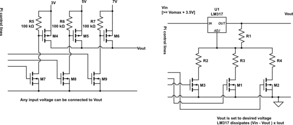
I have shown 2 3 5 7 volts rather than 5 6 7 V.
lter to suit.

I showed MOSFETS for M 5 6 7 and then realised that when Vot is more than about 0.5V above other supply voltages the MOSFET body diodes of any lower voltage supply will conduct. This can be avoided with back-to-back MOSFET pairs (annoying) or by using bipolar transistors for M 5 6 7 plus an extra base drive resistor in each case from M 7 8 9.

Left hand circuit:

Each of 3 existing voltages can be switched to Vout.
Dissipation in M4 ...6 is low
= Rdson x Iout^2

Right hand circuit:

LM317 regulator canm be set to any desired output Voltage > 1.25V and < Vmax_LM317.
Vout = 1.25V x (Rx + R1)/R1
Rx = any of R2 R3 R4.
Vout will rise to ~= Vin if all inputs are off. This can be avoided by replacing one output switch with a resistor set to provide the highest voltage (here 7V) and the lowering this with the other switched resistors.

Dissipation in LM317 is significant at high currents
= (Vin - Vout) x Iout.
LM317 has about 2V "dropout voltage" at higher currents.

schematic

simulate this circuit – Schematic created using CircuitLab

\$\endgroup\$
2
  • \$\begingroup\$ you don't need 3 switches to choose between 3 voltages choose r4 for 7V output and leave it connected all the time, chose r2 and r3 to parallel r4 for the lower voltages. \$\endgroup\$ Commented Nov 25, 2019 at 1:32
  • \$\begingroup\$ @Jasen - indeed - as per my text " ... by replacing one output switch with a resistor set to provide the highest voltage (here 7V) and the lowering this with the other switched resistors." -> There are pros and cons (as I'm sure you are aware). With 3 resistors each can be designed directly for the voltage concerned. With one fixed and two switched the lower voltages depend on the value, accuracy, drift and integrity of the highest voltage R. Whether this matters much deep-ends on the overall spec. \$\endgroup\$
    – Russell McMahon
    Commented Nov 25, 2019 at 1:57
1
\$\begingroup\$

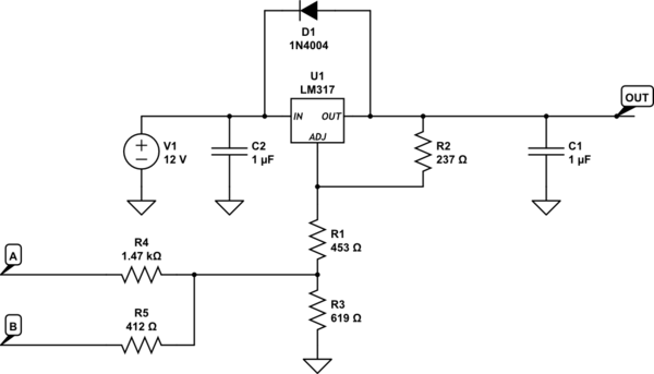
Here is a method that's a minor variation on Russell's method.

schematic

simulate this circuit – Schematic created using CircuitLab

With A & B both set to be inputs (no pullup or pulldown, use ST mode), output voltage is about 7V

with A set as output 0V, B set as input as above, output voltage is about 6V

With B set as output 0V, A set as input as above, output voltage is about 5V

If you intend to draw substantial current from the output, pay attention to the power dissipation. At 5V out, 100mA will result in about 735mW of dissipation, about where you will want a heatsink on a TO-220.

The resistor values are chosen so that no more than 3.3V appears at A or B. D1 is optional protection in case V1 can be shorted or subjected to a heavy load on turn-off. C1 and C2 are input and output capacitors. R2 sets the current through the resistor chain at a bit over 5mA.

\$\endgroup\$

Your Answer

By clicking “Post Your Answer”, you agree to our terms of service and acknowledge you have read our privacy policy.

Not the answer you're looking for? Browse other questions tagged or ask your own question.