0
\$\begingroup\$

I can't find the correct solution for this exercise and I can't figure out why.
schematic

simulate this circuit – Schematic created using CircuitLab

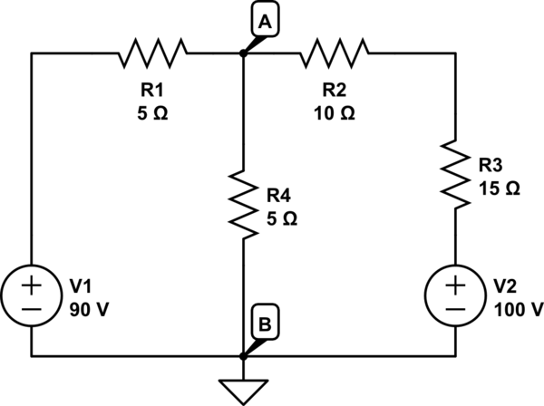
The question is: What is the current \$I_3\$ ? (answer: -2A).

I want to answer to this question using the node potential method. I chose the left -> right and top -> down direction for the current in every component. There are 2 nodes A and B so I can write \$(N-1) = 2-1 = 1\$ equation for the KCL. I chose the equation of B which is also the node set to potential 0 (ground).

\$-I_1 +I_4 +I_3 = 0\$

Note that \$I_1\$ is negative because the current in the voltage source is equal to the current in \$R_1\$ but with opposite direction (respectively top-down and left-right). Then I replace the currents in the equation above with the potentials:

\$-{ {B + E_1 - A} \over R_1 } + {{A - B} \over R_4 } + {{A - E_2 - B} \over R_3}\$

By removing B (=0) and by replacing the resistor and voltage values I obtain:

\$ A/5 + A/5 + A/15 = -90/5 + 100/15 \Rightarrow A = -170/7\$

Unfortunately replacing the variables with the values in \${{A - E_2 - B} \over R_3}\$ doesn't give the correct answer. Why is that ? Where is the error ?

\$\endgroup\$
3
  • \$\begingroup\$ I believe your equation $$A/5 + A/5 + A/15 = -90/5$$ is wrong. Observe that R2 and R3 are in series. I think you want $$A/5 + A/5 + A/25 = -90/5$$ \$\endgroup\$
    – Bob
    Commented Dec 5, 2019 at 0:03
  • 1
    \$\begingroup\$ There is no \$I_3\$ in your diagram. \$\endgroup\$
    – The Photon
    Commented Dec 5, 2019 at 2:38
  • \$\begingroup\$ @ThePhoton \$I_3\$ is the current flowing through the resistor \$R_3\$. I thought it would be obvious. \$\endgroup\$
    – Bemipefe
    Commented Dec 5, 2019 at 7:38

2 Answers 2

1
\$\begingroup\$

I am going to solve the circuit by using nodal analysis. The sum of the currents out of node A must be 0. \begin{align*} \frac{V_a - 90}{5} + \frac{V_a}{5} + \frac{V_a - 100}{25} &= 0 \\ 5(V_a - 90) + 5V_a + V_a - 100 &= 0 \\ 11V_a &= 550 \\ V_a &= 50 \\ I_3 &= \frac{50-100}{10+15} = \frac{-50}{25} \\ I_3 &= -2 \end{align*}

\$\endgroup\$
7
  • \$\begingroup\$ I didn't mark you down. But there are two problems with your answer that may have led to it being marked down. (1) The question doesn't indicate the direction of \$I_3\$. That's a fatal flaw in the question; and (2) You've provided the correct answers (given your assumption about the direction) and some people here don't like that. I'm not one that cares, because while the OP may not benefit so much from a "free answer" there are others who read along that may benefit from seeing how it is done. Just FYI. (Personally, I think you should only clarify your assumptions about the direction.) \$\endgroup\$
    – jonk
    Commented Dec 5, 2019 at 6:02
  • \$\begingroup\$ @jonk I actually specified what is the direction of the current: "I chose the left -> right and top -> down direction for the current in every component." So for \$I_3\$ is from node A to node B. \$\endgroup\$
    – Bemipefe
    Commented Dec 5, 2019 at 7:39
  • \$\begingroup\$ @Bob why do I need to use the resistance value resulting from the series of \$R_2\$ and \$R_3\$ (\$25 \Omega\$) ? I mean the circuits with the series and the circuit with the equivalent resistor are equivalent by definition. Furthermore the current flowing through \$R_2\$ and \$R_3\$ is the same. I don't understand why this approach is wrong. \$\endgroup\$
    – Bemipefe
    Commented Dec 5, 2019 at 7:53
  • \$\begingroup\$ @Bemi I now see that. Thanks for that. So I can remove my complaint about the question. Thanks for putting that out. My remaining comment to the answerer remains. Some folks don't like seeing full answers given away. \$\endgroup\$
    – jonk
    Commented Dec 5, 2019 at 14:41
  • 1
    \$\begingroup\$ The voltage drop \$V_a\$ includes both the voltage drop across \$R_1\$ and \$R_2\$ so that is why I wrote the divisor as \$25\$. However, if you transform the voltage source to a current source ( as down by Chuck Boyer ) then you do not need to do this. \$\endgroup\$
    – Bob
    Commented Dec 5, 2019 at 22:16
1
\$\begingroup\$

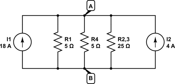
One approach is to associate each ideal voltage source with its adjacent resistor(s) to form a corresponding Thevenin source, which you then convert to its Norton equivalent current source:

schematic

simulate this circuit – Schematic created using CircuitLab

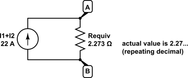
Then add the parallel ideal current sources and calculate the parallel resistance to get the following simple equivalent circuit:

schematic

simulate this circuit

This yields Vab = 50V, and you can now easily determine the branch currents into node A in the original circuit: 8A, -10A and 2A . Reverse the sign of each branch current to denote current flow away from node A.

\$\endgroup\$
2
  • \$\begingroup\$ I know that you can combine two parallel current source into one whose value is the sum of the currents provided by the original two. However I don't understand what allow you to do that in presence of a circuit (resistors in this case) between these two current source. \$\endgroup\$
    – Bemipefe
    Commented Dec 8, 2019 at 19:17
  • 1
    \$\begingroup\$ The Norton equivalent current sources are in parallel with the resistors that were in series with the original voltage sources. You can treat each original voltage sources and its corresponding resistor as the Thevenin equivalent circuit for a non-ideal voltage source. You can then transform the Thevinin source to its Norton equivalent current source. Here are Thevenin's Theorem: electronics-tutorials.ws/dccircuits/dcp_7.html and Norton's Theorem: electronics-tutorials.ws/dccircuits/dcp_8.html \$\endgroup\$ Commented Dec 9, 2019 at 6:08

Your Answer

By clicking “Post Your Answer”, you agree to our terms of service and acknowledge you have read our privacy policy.

Not the answer you're looking for? Browse other questions tagged or ask your own question.