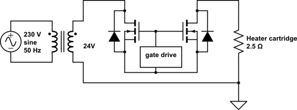
I'm planning on using a 120 VA Hammond 1182P12 toroidal transformer to deliver 24 VAC to a 2.5 Ω resistive load (a JBC C245 soldering iron cartridge), implying 9.6 A RMS, 230 W if continously applied. A microcontroller-driven solid state AC switch in series with the load would open or close at zero crossings, modulating the delivered power. A slow fuse would protect the device at the primary side.

simulate this circuit – Schematic created using CircuitLab
The transformer is rated for 5 A continous (at 24 V), and I suspect this limitation to be determined almost exclusively by the heating of the transformer due to losses. Mains transformer losses can be split into two components - core losses (hysteresis and eddy currents), which are mostly load invariant (determined by primary frequency and voltage) and copper losses, which are only proportional to the square of the load current (neglecting the small primary current present due to core losses).
Assuming a worst case scenario where all transformer losses are due to copper losses, half a cycle (50 ms) of operation at 9.6 A produces the same losses as 50 ms * (9.6 A)2 / (5 A)2 = 184 ms at the rated 5 A.
My control algorithm would make sure that:
DC balance is maintained to prevent core saturation (the number of positive half cycles delivered to the load always matches the number of negative ones, +/- one)
The average power delivered on a timescale of 10 minutes or more is always 85 W or less (with the above assumptions, 85 W average in the form of 9.6 A pulses generates the same copper losses as 5 A continous)
The average power delivered on a timescale of 5 s or more is always 140 W or less
Can I avoid a bulkier, heavier and more expensive transformer and larger case?
