3
\$\begingroup\$

I've got a cheopo BaoFeng UV-5RE that I'd like to try as packet radio.

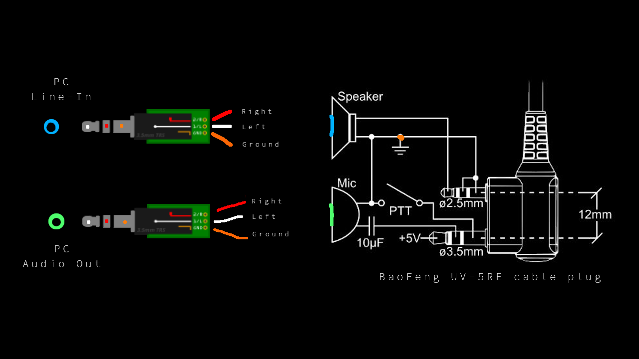
I've snipped the plug off of the headset that came with the handheld, soldered it onto some breadboard cables, and did the same to one 3.5mm jack plug connector intended to go in the soundcard. (I'd prioritize getting listening to work through line-in, first.)

But, having done that, at least one after thought hit me: the speaker-out on the BaoFeng is mono, while the port(s) on the soundcard is intended for stereo.

Would anyone be able to help me out with a wiring plan?

Feel free to doodle further on the image for rough illustration.

(Sorry for the hasty sketch. And I realize the line-in and out of the PC is perhaps in reverse location. I'm not entirely sure.)

BaoFeng to soundcard line-in/out wiring

Push-To-Talk is not very important per se, since the radio apparently have 'VOX' function, but if that's not recommended maybe I could use an Arduino that I got for the task some sort of (Linux) serial-PTT and perhaps also as some sort of a go-between the radio and the PC entirely?

Some (maybe) useful notes:

https://soundcardpacket.org/7cablerx.aspx (notes on 9600 baud cabling et.al)

https://ham.stackexchange.com/questions/1891/whats-the-pinout-for-kenwood-2-5mm-trs-3-5-mm-trs-connector

https://ham.stackexchange.com/a/3638 (this is where I found the plug image)

https://en.wikipedia.org/wiki/Line_level#Line_in

https://pinoutguide.com/Audio-Video-Hardware/Tele35s_pinout.shtml (the jackplug)

https://archive.org/stream/BaoFeng_UV-5R_manual (manual, with specs(?))

\$\endgroup\$

1 Answer 1

3
\$\begingroup\$

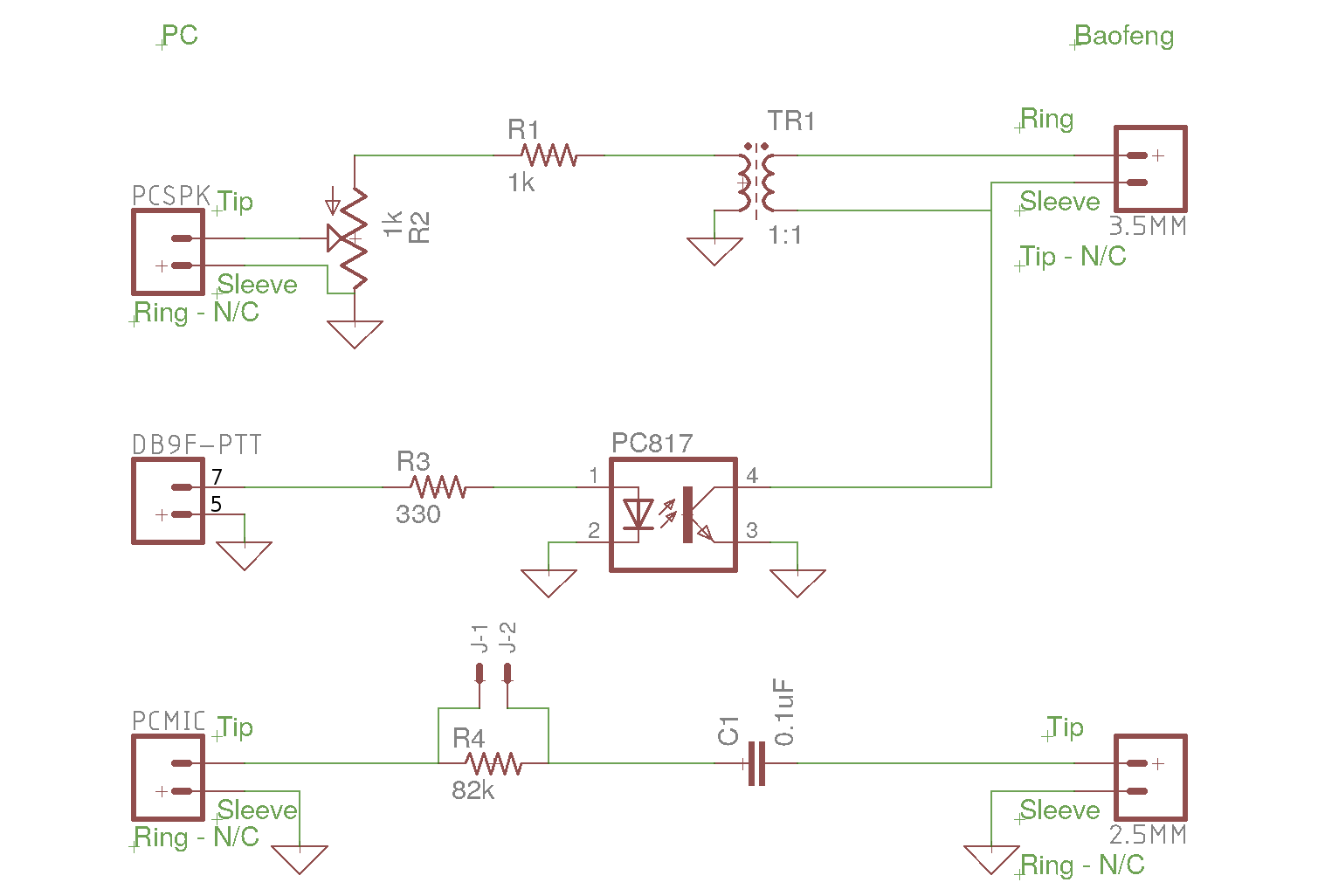
It looks like somebody solved the exact problem you are mentioning, and it requires an intermediate board between the sound card and the radio. Here is the suggested pinout:

Wiring Diagram

The original article can be found on https://k0rx.com/blog/2017/11/baofeng.html, but I copied the image in case it goes offline.

It is equally interesting to mention a solution which does not work: Basically, plain wiring of the appropriate cables to the input and output of your sound card will not do the trick if the sound card puts the grounds together, because shorting the sleeves is how you cause the PTT to transmit.

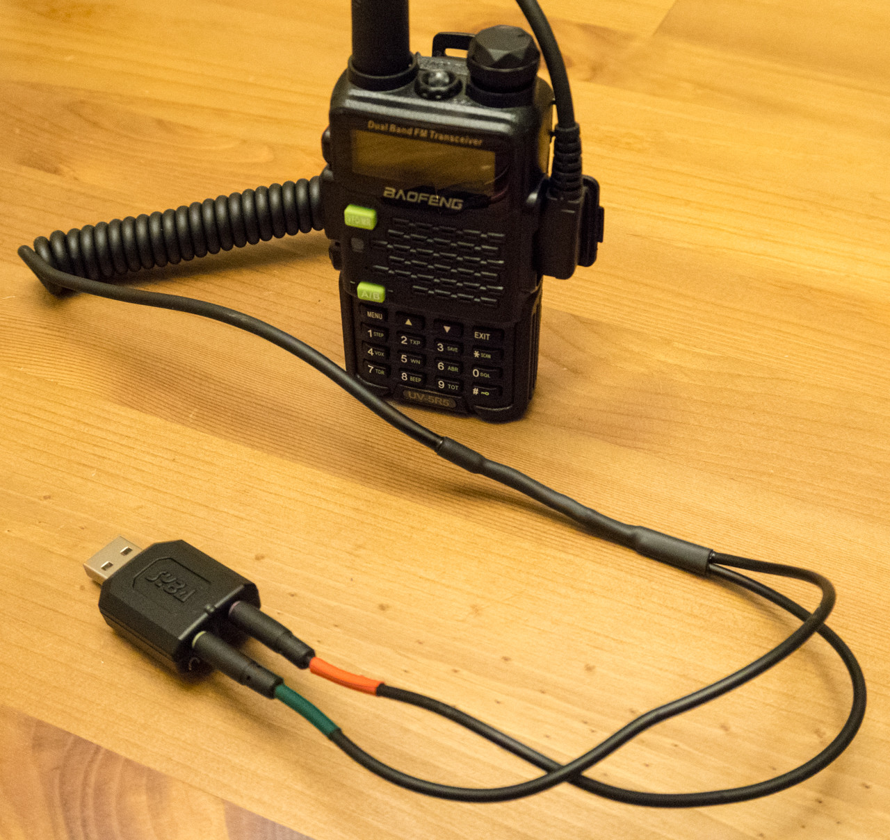
Now this isn't always the case, because I found somebody who put a cable together by cutting a double male jack, a 2-pins cable and doing some very simple soldering:

simple cable

However, I suspect that the fact it works is specific to the sound card.

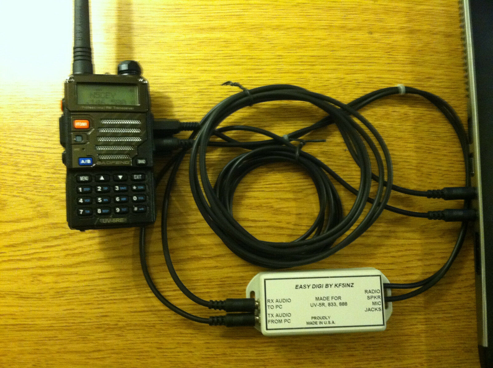
The board I mentioned seems to exist as a "commercial" solution (a hobbyist sells those on ebay). I won't paste an ebay link here as I suspect this is against the community policy, but here is a picture of it and it seems to be what you are looking for. I cannot recommend it myself, but this is where my own search has led me so far.

enter image description here

Edit: After giving it more thoughts, I figured a way to wire this without shorting the sleeves. When the PTT is open, you get the correct GND for the speakers. When the PTT is closed, MIC- and SPK- have the same potential, so you get the correct GND for the MIC.

enter image description here

Edit 2:

I believe that is how the person from highonsolder.com did it. However, they say that they must set the in and out of the sound card to very low volume for it to function correctly. That would be because the output of the card is set to line level. In that case, a voltage divider should do the trick to attenuate the signal and set it to mic level. Here is what I intend to try:

enter image description here

\$\endgroup\$
1
  • \$\begingroup\$ Thank you very much! :D \$\endgroup\$
    – DhP
    Commented Sep 6, 2020 at 20:11

Your Answer

By clicking “Post Your Answer”, you agree to our terms of service and acknowledge you have read our privacy policy.

Not the answer you're looking for? Browse other questions tagged or ask your own question.