4
\$\begingroup\$

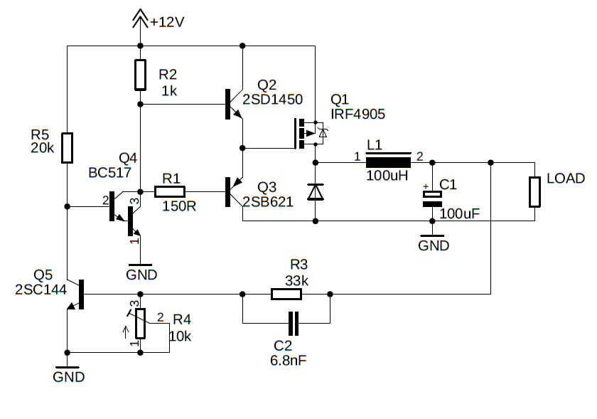
I tried to build a buck converter without any ICs, just transistors, a diode and passive components. Its purpose is to convert 12V to 5V at 2 Amps. It works, but the switching MOSFET (IRF4905) heats up very quickly and I can't figure out exactly what the issue is.

Buck converter circuit

The idea was to build a sort of hysteretic buck converter. R3 and the trimmer R4 form a voltage divider, when the voltage across R4 is high enough (about 0.7V), Q5 opens and closes Q4, which closes the MOSFET. If the voltage on the output is too low, the MOSFET is open.

It regulates the voltage, but it heats up very quickly at 2A. I measured the switching frequency to be about 42kHz. I suspect that the MOSFET is not opening and closing fast enough, or not opening and closing completely. I can't verify that because I don't have an oscilloscope.

List of things I tried:

  • Decreasing/increasing frequency by changing C2.
  • Increasing inductance L1 to ~280uH.
  • Adding a 1k resistor from the MOSFET gate to +12V.
  • Adding 100nF and 4.7uF capacitors between Vcc and GND near the totem pole.

Does anyone know what could cause the MOSFET to heat up? Any suggestions would be appreciated.

\$\endgroup\$
10
  • 4
    \$\begingroup\$ Welcome to EE.SE! Please show Vgs and Vds in the same oscillogram with good probing. You can’t develop an SMPS without an oscilloscope. \$\endgroup\$
    – winny
    Commented Dec 16, 2019 at 14:43
  • 1
    \$\begingroup\$ When EEs refer to opening and closing circuits we do it oppositely to that which a plumber might say thus, if a transistor "opens" it stops conducting and vice versa. Hence we have an open circuit that means there is no connection. Did it become too hot to touch? Heating up is expected. What flyback diode did you use? What inductor did you use? \$\endgroup\$
    – Andy aka
    Commented Dec 16, 2019 at 14:54
  • 1
    \$\begingroup\$ OK, I will try to use the terms properly next time. The transistor reaches 100°C in about 2 minutes. I used a schottky diode meant for switching power supplies (SR***). I'm not quite sure which one it is because I currently don't have the circuit near me. The inductor is a 100uH ferrite core inductor pulled from an old PC power supply. I later tried switching it for a 280uH toroidal core inductor. \$\endgroup\$
    – Wonka
    Commented Dec 16, 2019 at 15:16
  • 1
    \$\begingroup\$ The heating up of the P-MOSFET should not happen provided that it is switched on/off properly and quickly enough. Use an oscilloscope to monitor the Vgs of Q1. Also make sure that inductor L1 doesn't saturate. These are standard checks on any DCDC converter. I must state that it will be challenge to make a "good" 2A DCDC converter using only discrete components. \$\endgroup\$ Commented Dec 16, 2019 at 15:21
  • 2
    \$\begingroup\$ Note that if you live in a 1st-world country you're going to spend more money on the extra circuit board space than you would on some 20 year old jellybean switcher chip, like an MC33063 -- and the chip will perform better. Note, too, that if you're willing to do surface-mount, you'll spend less money on a brand new switcher chip that operates at 200kHz to 1MHz than you will on the inductor you'll need for a 40kHz, 10W switcher -- it's why the new chips sell. \$\endgroup\$
    – TimWescott
    Commented Dec 16, 2019 at 15:39

6 Answers 6

4
\$\begingroup\$

The transistor reaches 100°C in about 2 minutes.

The transistor unmounted on a heatsink has a thermal resistance of 62 degC per watt. That is how much it will heat up if dissipating a watt of power.

Its purpose is to convert 12V to 5V at 2 Amps

5 volts at 2 amps is 10 watts and losses in the MOSFET of about 1 watt (or a little more) are a likely scenario. Modern buck regulators are quite often quoted as having an efficiency of around 95% and a home spun one will be somewhat worse than this at around 90% so, I don't think your MOSFET is doing anything out of the ordinary.

It might continue to warm of course so you should consider mounting it on a small heatsink. Note that it does have a maximum operating temperature of 175 degC.

\$\endgroup\$
4
\$\begingroup\$

Sorry for not updating sooner. But I finally got the circuit to work.

I followed the advice that Russell McMahon gave me and I connected a 1 Megaohm resistor in parrallel with a 220pF capacitor from the base of Q5 to the collector of Q4. This should add positive feedback to the regulator.

The MOSFET barely heats up now and I measured the efficiency of the circuit to be around 81% with an input voltage of 12V and output of 5V at 2A. I will try to optimize it further but I think that most of the losses are from the freewheeling diode. A synchronous buck converter would be too complicated to make with discrete components, so I'll leave the diode.

It works better than I originally expected. And it should be possible to improve it further.

\$\endgroup\$
1
\$\begingroup\$

In the absence of a scope, I'd simulate that and see what's happening.

Probably what's going on is that you're correct and the FET isn't getting switched fast enough. Probably the least that you need to do is to add some positive feedback to the amplification stage at Q5. If I were determined to keep the circuit to only transistors, I'd add a capacitively-coupled PNP stage there that's set up with positive feedback so that Q5 switches, well, positively.

\$\endgroup\$
1
\$\begingroup\$

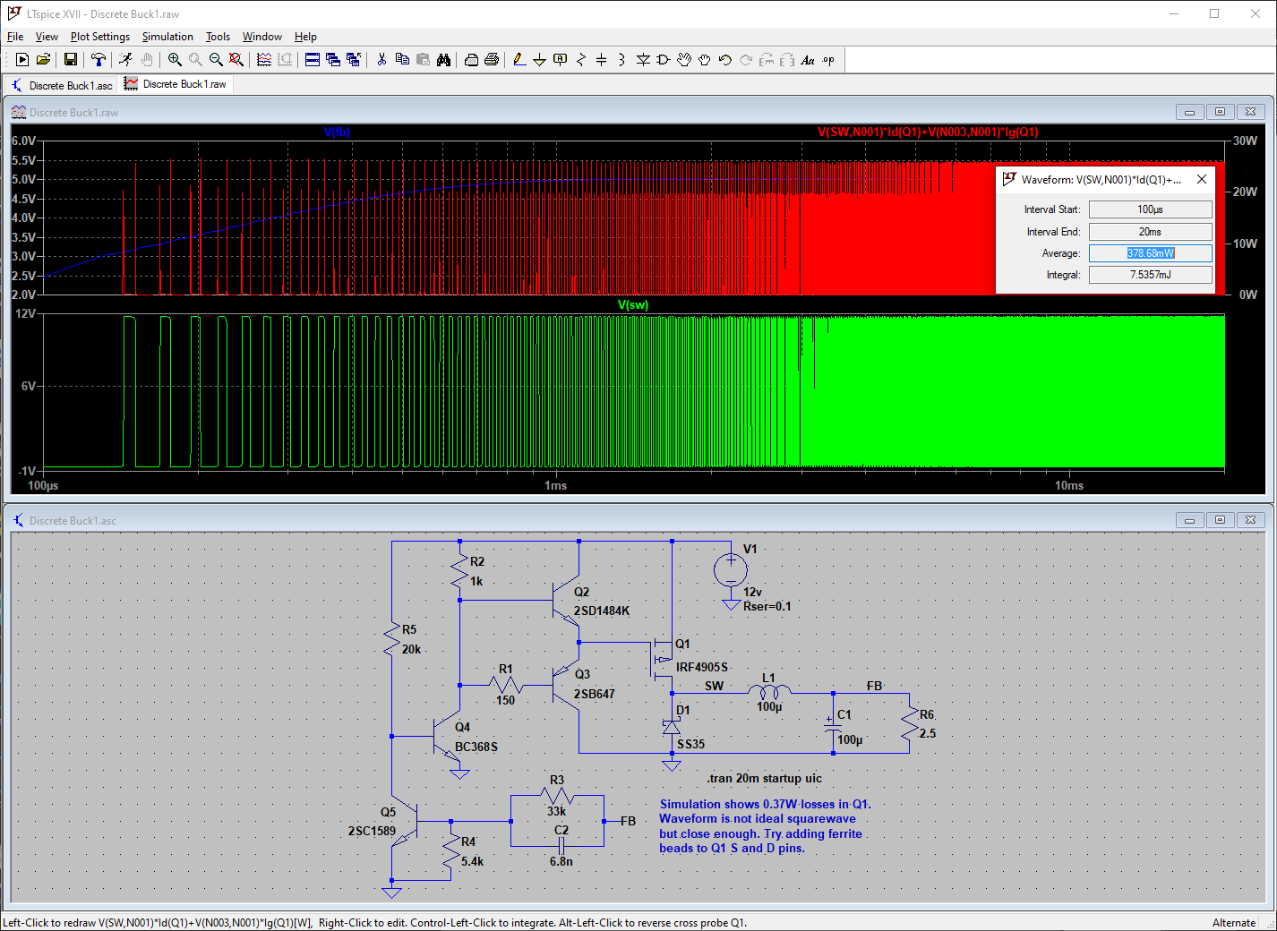
Here is an LTspice simulation of the schematic. Slightly different components were used due to library limitations, but even with these changes, the simulation works:

Discrete Buck simulation

The traces are plotted logarithmically to try and show both small and large-scale detail.

So the simulation looks promising. But the only way to know for certain what the circuit is doing is to 'scope the gate lead of Q1. The simulation does hint at some non-ideal rounding and delay on the gate lead, but it's not too bad considering the spartan component count. Another possibility is high-frequency ringing at the switched node; if you have any ferrite beads, try adding one to Q1. Short of that, you'll have to get an oscilloscope.

Here is the .asc file:

Version 4
SHEET 1 880 680
WIRE -160 -144 -288 -144
WIRE 64 -144 -160 -144
WIRE 240 -144 64 -144
WIRE 352 -144 240 -144
WIRE -160 -128 -160 -144
WIRE 352 -128 352 -144
WIRE 64 -80 64 -144
WIRE -160 -32 -160 -48
WIRE 0 -32 -160 -32
WIRE 352 -32 352 -48
WIRE -288 0 -288 -144
WIRE 240 32 240 -144
WIRE 64 48 64 16
WIRE 192 48 64 48
WIRE 64 80 64 48
WIRE -160 128 -160 -32
WIRE -112 128 -160 128
WIRE 0 128 -32 128
WIRE 240 144 240 128
WIRE 320 144 240 144
WIRE 384 144 320 144
WIRE 544 144 464 144
WIRE 624 144 544 144
WIRE 688 144 624 144
WIRE 688 160 688 144
WIRE -160 176 -160 128
WIRE 240 176 240 144
WIRE 544 176 544 144
WIRE -288 224 -288 80
WIRE -224 224 -288 224
WIRE 64 256 64 176
WIRE 240 256 240 240
WIRE 240 256 64 256
WIRE 544 256 544 240
WIRE 544 256 240 256
WIRE 688 256 688 240
WIRE 688 256 544 256
WIRE 240 272 240 256
WIRE -160 288 -160 272
WIRE -288 336 -288 224
WIRE -16 336 -64 336
WIRE 112 336 64 336
WIRE -176 384 -224 384
WIRE -64 384 -64 336
WIRE -64 384 -176 384
WIRE 112 384 112 336
WIRE 144 384 112 384
WIRE -176 400 -176 384
WIRE -64 432 -64 384
WIRE 0 432 -64 432
WIRE 112 432 112 384
WIRE 112 432 64 432
WIRE -288 496 -288 432
WIRE -176 496 -176 480
WIRE -176 496 -288 496
WIRE -288 512 -288 496
FLAG 624 144 FB
FLAG 144 384 FB
FLAG 240 272 0
FLAG -288 512 0
FLAG 352 -32 0
FLAG -160 288 0
FLAG 320 144 SW
SYMBOL pmos 192 128 M180
WINDOW 0 55 78 Left 2
WINDOW 3 56 33 Left 2
SYMATTR InstName Q1
SYMATTR Value IRF4905S
SYMBOL schottky 224 240 M180
WINDOW 0 24 64 Left 2
WINDOW 3 24 0 Left 2
SYMATTR InstName D1
SYMATTR Value SS35
SYMATTR Description Diode
SYMATTR Type diode
SYMBOL ind 368 160 R270
WINDOW 0 32 56 VTop 2
WINDOW 3 5 56 VBottom 2
SYMATTR InstName L1
SYMATTR Value 100µ
SYMATTR SpiceLine Ipk=5 Rser=0.028 Rpar=0 Cpar=0 mfg="Coiltronics" pn="CTX100-5-52"
SYMBOL polcap 528 176 R0
WINDOW 3 24 56 Left 2
SYMATTR InstName C1
SYMATTR Value 100µ
SYMATTR Description Capacitor
SYMATTR Type cap
SYMATTR SpiceLine V=10 Irms=3.87298 Rser=0.015 Lser=0 mfg="KEMET" pn="A700X107M010ATE015" type="Al electrolytic"
SYMBOL res 672 144 R0
SYMATTR InstName R6
SYMATTR Value 2.5
SYMBOL res 80 320 R90
WINDOW 0 0 56 VBottom 2
WINDOW 3 32 56 VTop 2
SYMATTR InstName R3
SYMATTR Value 33k
SYMBOL cap 64 416 R90
WINDOW 0 0 32 VBottom 2
WINDOW 3 32 32 VTop 2
SYMATTR InstName C2
SYMATTR Value 6.8n
SYMBOL res -192 384 R0
SYMATTR InstName R4
SYMATTR Value 5.4k
SYMBOL npn -224 336 M0
SYMATTR InstName Q5
SYMATTR Value 2SC1589
SYMBOL npn -224 176 R0
SYMATTR InstName Q4
SYMATTR Value BC368S
SYMBOL pnp 0 176 M180
WINDOW 0 58 68 Left 2
WINDOW 3 56 31 Left 2
SYMATTR InstName Q3
SYMATTR Value 2SB647
SYMBOL npn 0 -80 R0
SYMATTR InstName Q2
SYMATTR Value 2SD1484K
SYMBOL res -176 -144 R0
SYMATTR InstName R2
SYMATTR Value 1k
SYMBOL res -16 112 R90
WINDOW 0 0 56 VBottom 2
WINDOW 3 32 56 VTop 2
SYMATTR InstName R1
SYMATTR Value 150
SYMBOL res -304 -16 R0
SYMATTR InstName R5
SYMATTR Value 20k
SYMBOL voltage 352 -144 R0
WINDOW 123 0 0 Left 0
WINDOW 39 24 124 Left 2
SYMATTR InstName V1
SYMATTR Value 12v
SYMATTR SpiceLine Rser=0.1
TEXT 306 304 Left 2 !.tran 20m startup uic
TEXT 216 352 Left 2 ;Simulation shows 0.37W losses in Q1.\nWaveform is not ideal squarewave\nbut close enough. Try adding ferrite\nbeads to Q1 S and D pins.
\$\endgroup\$
1
\$\begingroup\$

I also agree with Hearth that your FET (R DS(on) = 0.02Ω) was operating in partial linear mode except you were able to measure a frequency of 42kHz at 5V 2A.

I suggest this design is inferior because the oscillator is not stable and depends on parasitics with phase margin reduced by the 5 transistor stages and Series Resonant Frequency of a couple hundred Hz with selected LC values.

The FET is overkill for a 2 A load rated for > 50A with 260A peaks but that adds to the Coss and very low RdsOn to cause spurious resonance where the phase margin must be negative in order to sustain oscillation.

There may be ways to increase the gate drive to a sharp pulse but it is not worth the overkill on FET switch and unstable design.

The PFET also guarantees high inrush power on start driving the ESR of the load capacitor then the inductor saturates.

All around , I'd say it's not surprising that it can regulate or oscillate but the load regulation is terrible without a voltage reference and step load overshoot for a wide range of loads would be terrible.

Conclusion.
The major missing ingredients to a good SMPS regulator design are " Good Specs, and good tolerance margins."

Poor topology.

\$\endgroup\$
2
  • 1
    \$\begingroup\$ The load regulation and overshoot is not that important for what I need. I just want to reduce the heating and improve efficiency. \$\endgroup\$
    – Wonka
    Commented Dec 16, 2019 at 19:11
  • \$\begingroup\$ Like I said, where are your design specs? You have a nice sine wave oscillator with 5Vdc. You need a pulse oscillator for the Gate regulated with a Vref \$\endgroup\$
    – D.A.S.
    Commented Dec 16, 2019 at 19:22
0
\$\begingroup\$

I've run a simulation, and it doesn't look like your FET is switching at all. I think you may have built what amounts to a linear regulator, instead of a switching one; there's some oscillatory behavior when the potentiometer is changed, but it decays away into a stable linear mode rather quickly.

Under the assumption that you have accidentally made a linear regulator, the switching element heating up is to be expected. With the 2.5 Ω load, the power dissipation in the transistor is over 13 watts, which is more than enough to heat it substantially even with a decently-sized heatsink.

\$\endgroup\$
12
  • \$\begingroup\$ I measured the frequency on the FET's gate using a multimeter and it shows about 42kHz. I also measured the ac voltage on it and it shows about 5V RMS. \$\endgroup\$
    – Wonka
    Commented Dec 16, 2019 at 17:52
  • \$\begingroup\$ @Wonka Seems my simulation is missing something then, perhaps parasitics affect circuit operation or maybe the simulator is flawed somehow. \$\endgroup\$
    – Hearth
    Commented Dec 16, 2019 at 18:00
  • \$\begingroup\$ What simulator did you use? \$\endgroup\$
    – Wonka
    Commented Dec 16, 2019 at 19:14
  • \$\begingroup\$ @Wonka CircuitJS. \$\endgroup\$
    – Hearth
    Commented Dec 16, 2019 at 19:14
  • \$\begingroup\$ falstad.com/circuit/circuitjs.html \$\endgroup\$
    – Wonka
    Commented Dec 16, 2019 at 19:15

Your Answer

By clicking “Post Your Answer”, you agree to our terms of service and acknowledge you have read our privacy policy.

Not the answer you're looking for? Browse other questions tagged or ask your own question.