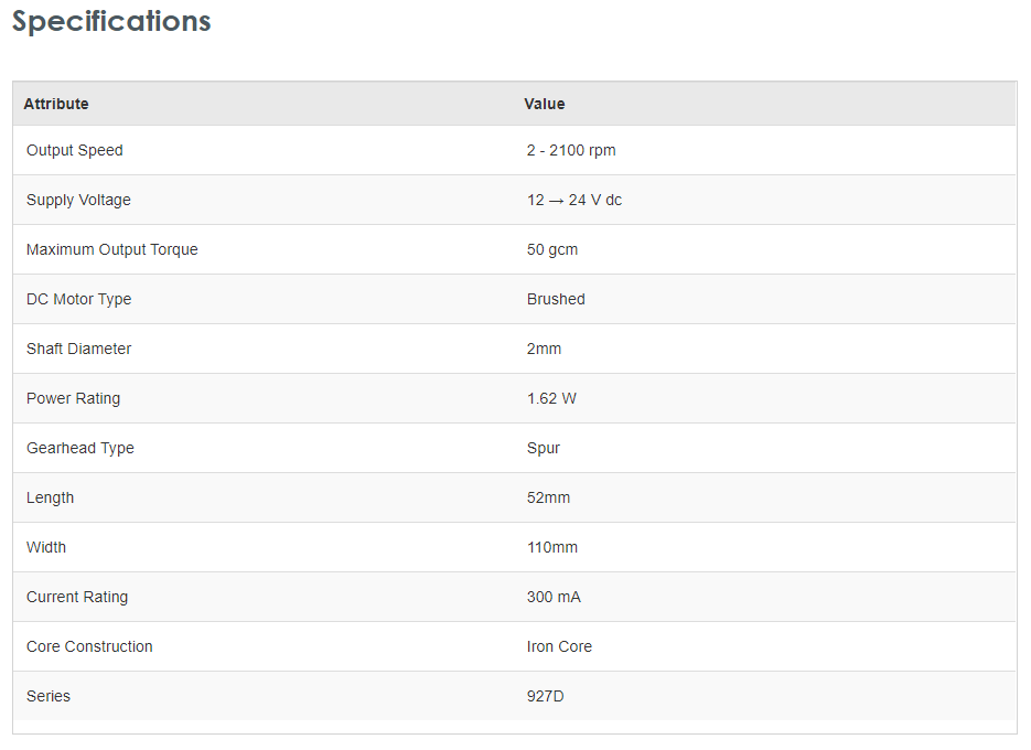
I want to control the speed of this brushed DC motor with PWM control by using a uC board like an Arduino board. So the PWM output is 5V and it can source only upto 20mA so I need to use a transistor buffer. The DC motor specs are given as following:
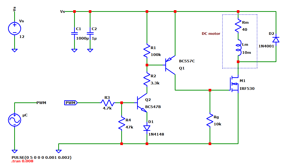
And below is the driver circuit I plan to use. Before soldering I have some questions not settled, I merged a transistor buffer with this power MOSFET I have at the moment. I only have these transistors at the moment. And I want a non-inverting logic. I mean when PWM is 100% the motor should run at full speed and vica versa. That's why I use two bipolar and drive the load(motor) on the upper side of the MOSFET. PWM frequency can be 500Hz up to 24kHz. Not decided yet.
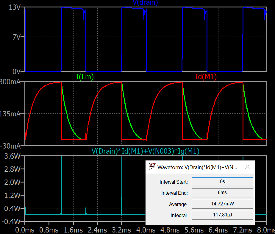
When I simulate the MOSFET drain voltage, drain current, motor current and the MOSFET power I get the following plots(PWM freq in this case is 500Hz):
1-) If there is not fundamental problem with this driver circuit, how can I model the DC motor? I modeled it as L and R series but the values are based on assumption. Is it correct to estimate motor resistance Rm from the specs as 24/0.3A = 72 Ohm? How about the inductance? Is 1mH realistic?
2-) And from the MOSFET data sheet, upto what max current this MOSFET can handle without a heatsink? I'm asking because I might change the motor voltage or use similar type of motor with more current.


