0
\$\begingroup\$

After I saw lots of simulations with CircuitLab here I subscribed today. And then I tried to simulate a simple circuit with an OpAmp which did not work as expected because I could not "measure" the current on the voltage rails of the OpAmp.

I simplified the schematic and here it is. When I simulate it the current on RL is between 0 to 15mA and the voltage between 0 and 3.5V. So far ok.

But if I measure the current on the OpAmp + and - rails the current it 0. I would have expected that the current on the positive rail is the same as the outgoing current.

What is wrong here? Does the CircuitLab simulation not work with this OpAmp (from their list) or does the current simulation on the OpAmp rails not work with any OpAmp or do I do something wrong here?
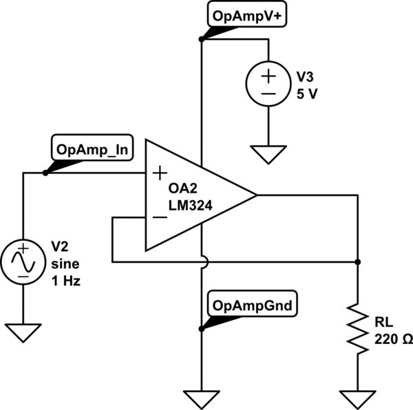
schematic

simulate this circuit – Schematic created using CircuitLab

\$\endgroup\$

1 Answer 1

1
\$\begingroup\$

I think CircuitLab doesn't simulate the power draw by the opamp (neither for the output, nor for the quiescent current needed by the IC innards).

The reason for this, I guess, is that LM324 is a jellybean part, made by a handful of manufacturers, so if you truly want to simulate, you would need to specify exact part number and manufacturer, not just "LM324". If you go that direction, then it's probably best to use the manufacturer's SPICE models for that opamp, even though I'm not sure if they simulate the quiescent current as well, but it's more likely that they do.

E.g. I just tried similar to your schematic in LTspice and it seems they simulate the power rails, I was able to measure the current going in the opamp.

\$\endgroup\$

Your Answer

By clicking “Post Your Answer”, you agree to our terms of service and acknowledge you have read our privacy policy.

Not the answer you're looking for? Browse other questions tagged or ask your own question.