0
\$\begingroup\$

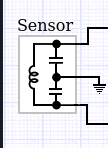
I have a water level sensor in which by varying the level of the water, an inductance change his value in a mobile coil. The sensor have the internal simple schematic like this (i don't know the value of the components)

enter image description here

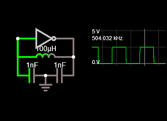
The suggested working circuit use a Colpitts oscillator made by some HEX inverters, producing a frequency from 21 kHz to 25 kHz linked to the coil position and at the end to the water level by a provided lookup table.

I should read this frequency (level) by a micro, and I know how to do it, but in my project I used all the internal microcontroller timers. So, what I would ask, is if I can get around, using this variable inductance to produce a variable voltage to be read by the micro (avoiding to measure a frequency). And if it was possible avoiding a cascade of a Colpitts oscillator and a Frequency-Voltage converter (like the LM311).

\$\endgroup\$
1

3 Answers 3

0
\$\begingroup\$

You could buffer the oscillator output, then put it through a carefully designed low pass filter. You could do this in a number of ways, like R-C passively, or actively as a second stage, or incorporated into the buffer.

\$\endgroup\$
2
  • 1
    \$\begingroup\$ I'm unsure of how this would translate into something measurable. What would low passing the sine/square wave accomplish? \$\endgroup\$ Commented Dec 30, 2019 at 0:40
  • 1
    \$\begingroup\$ @Michael sorry you are right... that only works as duty cycle conversion, not frequency conversion... maybe this will help google.com/url?sa=t&source=web&rct=j&url=https://… \$\endgroup\$
    – vicatcu
    Commented Dec 30, 2019 at 1:42
0
\$\begingroup\$

connect one end to one GPIO and the other end to another, test the pulse resposnse.

that's pretty much how "328 Mega LCR" works.

\$\endgroup\$
3
  • \$\begingroup\$ How does that work if there are no more timer resources? \$\endgroup\$
    – Dave Tweed
    Commented Dec 30, 2019 at 0:11
  • \$\begingroup\$ the processor clock is still available: run a tight loop counting and hope for no interrupts (or detect and retry, or disable) \$\endgroup\$ Commented Dec 30, 2019 at 0:12
  • \$\begingroup\$ What "328 Mega LCR" stay for? \$\endgroup\$
    – daigs
    Commented Dec 31, 2019 at 1:04
0
\$\begingroup\$

The frequency can be measured to determine change of C due to water Dk= 80 x air. This C change can be correlated with fluid height.

enter image description here

If you really cannot figure out how to share or better utilize your HW timers , get a counter with a serial interface and measure frequency somehow then calibrate it.

\$\endgroup\$
3
  • \$\begingroup\$ Can you explain better to me how to proceed? I didn't realize well the "serial counter interface". Thanks. \$\endgroup\$
    – daigs
    Commented Dec 31, 2019 at 0:51
  • \$\begingroup\$ do I have to explain how to measure frequency with an accurate time interval and counter? circuits4you.com/2016/05/13/arduino-frequency-counter \$\endgroup\$
    – D.A.S.
    Commented Dec 31, 2019 at 0:59
  • \$\begingroup\$ No thanks, I already measure other signals with both the arduino interrupts and timer in my project and as you can see from the question i have timers busy. Timer 0 is used for millis() and timer1 as another frequency counter. Timer 2 is not enough for the scope. Interrupt 0 and 1 are already used too. Your statement "serial interface" got me out of the solution you intended for. I could share the Timer1 stopping a process and start another, but I would use another approach if it exist for the problem, than Colpitts, like a direct voltage variation linked to the LC variation. \$\endgroup\$
    – daigs
    Commented Dec 31, 2019 at 15:09

Your Answer

By clicking “Post Your Answer”, you agree to our terms of service and acknowledge you have read our privacy policy.

Not the answer you're looking for? Browse other questions tagged or ask your own question.