0
\$\begingroup\$

I am an electronics novice.

I have a vintage calculator with six secondary wires coming out of its transformer and ending on the board, as shown below:

enter image description here

Using the AC portion of the multimeter, I measured the voltages across the board terminals marked 1 through 6, with the results as follows:

enter image description here

Is it normal to see AC voltages on such a board, or is this because of the age of the product (1979)?

Is the AC voltage changed to DC somewhere on the board?

Is this a "digital" calculator? (There is an IC chip on the board.) If so, why is there alternating current, unlike say on an Arduino?

\$\endgroup\$
2
  • 2
    \$\begingroup\$ The transformer basically takes one AC signal (attached to the primary) and converts it to AC signals of other voltages (secondary, tertiary windings, etc.) Circuity in then converts this AC to DC ("rectification"). If you have such a transformer, you can use a single voltage off the wall (120 Vac in the US) to create several voltages to supply different parts of your circuit. For example, the vacuum fluorescent display in your calculator takes a different voltage than the digital circuitry, but both are required for proper operation and both can be pulled off a properly designed transformer. \$\endgroup\$
    – Bort
    Commented Jan 6, 2020 at 19:16
  • \$\begingroup\$ Your numbers don't make a lot of sense. For example if V1_6 = and V1_5 are both 4.5V then V5_6 can't be larger than 9V. If these measurements are indeed correct, than there is more going on than a simple AC transformer. \$\endgroup\$
    – Hilmar
    Commented Jan 6, 2020 at 20:23

4 Answers 4

1
\$\begingroup\$

Yes, it's normal on a PCB with a mains-frequency power transformer to see AC voltages from the transformer. They can be rectified (diodes or bridge rectifier), filtered (those can electrolytic capacitors) and regulated, as required.

That calculator has a vacuum fluorescent display, which uses relatively high voltage for the grids and cathodes (something like 24VDC, often negative with respect to ground, is typical) and also has a filament which is typically a volt or two, and can be driven by AC or DC (possibly directly from a transformer winding in this case). Here is some more information on driving these displays.

The calculator IC itself probably runs from a few volts DC. There may be an external chip to drive the display, since the voltage requirements would tend to point to an IC process that would have been costly for the calculator IC.

Because of the multiple voltages, it's going to be very easy to damage the ICs by even a momentary short, so be careful probing.

\$\endgroup\$
1
\$\begingroup\$

Transformers work on AC, not DC. AC voltages can be converted to DC onboard if necessary. Just by looking at the PCB traces it can be guessed that there is a diode bridge for rectifying and the big electrolytic capacitor is the reservoir capacitor. Some AC voltages may be used directly such as the heating filament for the vacuum fluorescent display. But ICs need DC voltages, both digital or analog chips.

\$\endgroup\$
1
  • \$\begingroup\$ Thank you, upvoted. I am now researching reservoir capacitors. \$\endgroup\$
    – Sabuncu
    Commented Jan 7, 2020 at 7:19
1
\$\begingroup\$

it is certainly possible to have AC transformers on old circuits and transformers of this size were common until higher frequency transformers came into play in recent decades.

To your question on whether the voltage from this transformer would have been converted to a DC voltage onboard, the most likely answer is yes. Because almost all logic chips even those before modern microprocessors came in operated with a DC voltage. Some onboard rectifier and capacitors maybe doing the job of this conversion.

If there is a chip on board and a digital display then yes it would qualify as a Digital calculator(the definition of digital has quite evolved overtime though). One reason why modern boards like Raspberry Pi or Arduino donot have any AC transformers around is because with advent of modern switching power electronics, transformers and the circuitry required to convert voltages have become really small and can safely be fitted into small adapters which eventually supply standardized 5V, 12V or so voltages. So availability of low cost standard power supply modules mean designers today can focus entirely on core functionality of their circuits and use off the shelf, low cost and standardized devices to manage AC to DC power conversion.

If it is really needed and you wish to understand the functionality of this specific transformer in detail it could be worth using a milli Ohm meter/LC meter to measure winding resistances/Inductances which would give some clues on construction of this transformer and whether they are isolated or combined (or by looking at the signals through an oscilloscope)

Hope this helps.

\$\endgroup\$
1
  • \$\begingroup\$ Thank you so much, very helpful. \$\endgroup\$
    – Sabuncu
    Commented Jan 6, 2020 at 19:53
1
\$\begingroup\$

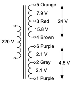
Looking at this question with your previous question in mind, the information is consistent with the transformer configuration shown below. The measured voltages don't quite add up to 4.5 and 24 volts, bit they are close enough. The continuity test does not show a connection between the two secondaries, but the voltage readings would indicate that there is some connection between the circuits powered by the two secondaries. The voltages between the terminals of one secondary and the terminals of the other are only important if they indicate a fault. They do not necessarily indicate a fault. Since the calculator is working, it seems likely that a common point may have been purposely created for the various DC power supplies. To understand the design, it would be useful to identify the common point for the DC circuits.

enter image description here

\$\endgroup\$
0

Your Answer

By clicking “Post Your Answer”, you agree to our terms of service and acknowledge you have read our privacy policy.

Not the answer you're looking for? Browse other questions tagged or ask your own question.