1
\$\begingroup\$

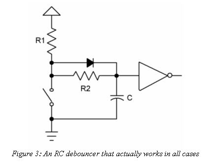
I want to use a momentary, normally open, SPST switch to act as a clock pulse on 16x2 character display. Of course, my switch has some bounce so I was looking at debouncing circuits and I always see the same one that uses an RC circuit in conjunction with a schmitt trigger inverter. For example, this one (which includes an extra diode that some folks use and some don't):

RC debounce circuit

The problem I see with this circuit (if I understand it correctly) is that the capacitor starts out at 0v, then charges up, which should result in the circuit putting out a high-to-low transition when it powers on the initially.

Am I misunderstanding this, or do most folks not care about that initial transition?

\$\endgroup\$
6
  • \$\begingroup\$ If you want to avoid a pulse on power Up, use cap from Vcc to input. , 2) remove R2, 3) reverse Diode to activate on leading edge . Choose RC=T> Bounce time ~1 to 10ms typ. so choose 20ms \$\endgroup\$
    – D.A.S.
    Commented Jan 6, 2020 at 22:14
  • \$\begingroup\$ That figure 3 comes from Jack Ganssle's runaway article on debouncing. Did you already read the text that comes with that document? \$\endgroup\$
    – jonk
    Commented Jan 7, 2020 at 5:00
  • \$\begingroup\$ @TonyStewartSunnyskyguyEE75 That was what I was thinking of doing. I'm going to get out my breadboard and play with that setup soon. \$\endgroup\$
    – Matthew
    Commented Jan 7, 2020 at 16:11
  • \$\begingroup\$ @jonk Actually, I just grabbed that picture from another question in order to have a visual. Thanks for the link, will definitely have a look! \$\endgroup\$
    – Matthew
    Commented Jan 7, 2020 at 16:12
  • \$\begingroup\$ @Matthew How did you solve the problem? \$\endgroup\$
    – Jay Lee
    Commented Jan 18, 2020 at 8:10

3 Answers 3

2
\$\begingroup\$

The cap charges through R1 and the diode when the switch is open, and sit at a diode drop below Vcc, producing a LOW on the output of the schmitt inverter. So yes, the output is high until the cap is charged. Any system using this will need to deal with the initialization transient.

\$\endgroup\$
1
\$\begingroup\$

If that initial pulse is an issue for you, just take the capacitor to Vcc, R1 to ground, and reverse the diode.

\$\endgroup\$
0
\$\begingroup\$

It depends on if the circuit is sensitive to that first edge or not. For example command 0x00 would not be a command anyway. Or the time for the edge is such that the display ignores it. Obviously you can wire the input to schmitt trigger so that there is no first edge, maybe rearranging components or using a normally closed switch or adding an inverter on the output.

\$\endgroup\$
1
  • \$\begingroup\$ I did think of doing just that, ensuring that the RS was set to command and the command was all 0's on initialization. Mainly I wanted to make sure I wasn't just wrong about the initial pulse due to the fact that every site I saw that posted a circuit like this completely ignored it. \$\endgroup\$
    – Matthew
    Commented Jan 7, 2020 at 16:13

Your Answer

By clicking “Post Your Answer”, you agree to our terms of service and acknowledge you have read our privacy policy.

Not the answer you're looking for? Browse other questions tagged or ask your own question.