0
\$\begingroup\$

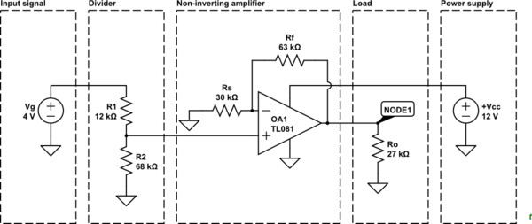
Here is my simple circuit. I would like to test whether the output is correct as per manual calculation. According to manual calculation, Gain=3.1, Vo=10.54V.

My question are:

  • How do I do that calculation?
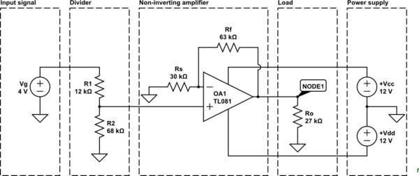
  • Is my way to do +Vcc and -Vc connection correct? Which both should be connected to +12V and -12V respectively.

schematic

simulate this circuit – Schematic created using CircuitLab

\$\endgroup\$
5
  • \$\begingroup\$ Your power connection is incorrect. There are many examples on the internet. \$\endgroup\$
    – Andy aka
    Commented Jan 11, 2020 at 12:51
  • \$\begingroup\$ Try it yourself $$V_O = Vg \frac{R_2}{R_1 + R_2} \times \left(1 +\frac{R_F}{R_S}\right)$$ \$\endgroup\$
    – G36
    Commented Jan 11, 2020 at 12:51
  • \$\begingroup\$ I am asking, How do I do calculation in CircuitLab. \$\endgroup\$ Commented Jan 11, 2020 at 14:40
  • \$\begingroup\$ @G36, your formula is correct. Using that formula will get V Thavenin (VTh) = 3.4V, and the gain is (1+63k/30k)=3.1. The Vo=VTh*gain=10.54V. But I want to verify that calculation using CircuitLab as I want to calculate another problem. \$\endgroup\$ Commented Jan 11, 2020 at 15:11
  • 1
    \$\begingroup\$ I do not understand, Simply left-click on "simulate this circuit" under your circuit. And click on the bottom "Simulate" -->"Run DC Solver" And then point a click on the node you want to "display the voltage". i.sstatic.net/nfs6f.png \$\endgroup\$
    – G36
    Commented Jan 11, 2020 at 15:28

2 Answers 2

2
\$\begingroup\$

According to manual calculation, Gain = 3.1, Vo = 10.54 V.

Nope. You're feeding 4 V in so a gain of 3.1 would give an output of 12.4 V. Something wrong somewhere.

schematic

simulate this circuit – Schematic created using CircuitLab

Figure 1. Redrawn schematic to show the circuit blocks.

How do I do that calculation?

Break down the circuit into its functional blocks.

  1. The input signal is 4 V and fixed. That's easy.
  2. Next you have a potential divider. (This is the part missing in your overall gain calculation.) The output of that is given by the ratiometric division $$ V_O = \frac {R1}{R1 + R2} Vg $$.
  3. This is followed by, what should now be obvious, a non-inverting amplifier stage. The output of this is given by $$ V_O = ( 1 + \frac {R_f}{R_s} ) V_I $$
  4. Next is the load. This doesn't affect the output provided we don't overload it. 27 kΩ will be fine.
  5. The power supply becomes important because an op-amp output can't go above the positive supply voltage and can't go below the negative supply voltage. In most cases it can't get within a couple of volts of either supply rail so we'll come back to this later.

The output of your circuit will be the product of all the stages that affect the signal; the divider and the non-inverting amplifier. $$ V_O = V_g \frac {R1}{R1 + R2}( 1 + \frac {R_f}{R_s} ) $$

Is my way to do +Vcc and -Vc connection correct? Which both should be connected to +12V and -12V respectively.

Now we come back to the power supply.

  • Your input signal of 4 V is driving the output to 10.5 V which is only 1.5 V from positive supply. You need to check the op-amp datasheet to see if it is capable of getting that close to positive supply. Some are. Some aren't.
  • The power supply limits the maximum input signal. If Vg > 4 V then you need to raise the 12 V to a higher voltage.
  • As Vg is decreased towards 0 V the op-amp may reach the lower output limit. If this is a problem you need to choose an op-amp that can output to negative rail or use a negative supply rail.

schematic

simulate this circuit

Figure 2. Split rail powered version.

enter image description here

Figure 3. Internals of the ancient 741 opamp. Source: Wikipedia.

Most opamps will have an output arrangement similar to the push-pull arrangement of the old 741. Others will have FET transistors rather than BJTs. In either case if the top transistor (red oval) is turned on the output will be pulled to positive rail. If the bottom transistor (green oval) is turned on the output will be pulled to negative rail. How close they get depends on the exact output configuration and the driving circuitry.


Answering the questions in the title:

How do I do calculation in CircuitLab?

For this example you just run the DC solver. This is simplest if you attach a NODE to your input, Vg, and your output, Ro. Simulate | DC Solver | Click each of the nodes to add them in | Run.

How do I provide +Vcc and -Vcc to the op-amp?

See my Figure 2.

\$\endgroup\$
11
  • \$\begingroup\$ I got the circuit and that calculation from this video: You may jump to minute 4:53. And that the thing I want to verify. But is it using 741. \$\endgroup\$ Commented Jan 11, 2020 at 14:47
  • \$\begingroup\$ Unfortunately I could not see any image due to blocked/filtered by service provider. \$\endgroup\$ Commented Jan 11, 2020 at 14:48
  • \$\begingroup\$ Sorry, why do I need to watch a video? Are you saying you can't see the images in my answer? \$\endgroup\$
    – Transistor
    Commented Jan 11, 2020 at 14:48
  • \$\begingroup\$ As you claimed that the calculation is wrong. That calculation is no mine. \$\endgroup\$ Commented Jan 11, 2020 at 14:49
  • \$\begingroup\$ The presenter already accounted for the attenuator (voltage divider) and at that point in the video is looking at the amplifier stage. I looked at the whole lot. You need to look at my answer using a different provider or via some sort of proxy. \$\endgroup\$
    – Transistor
    Commented Jan 11, 2020 at 14:54
0
\$\begingroup\$

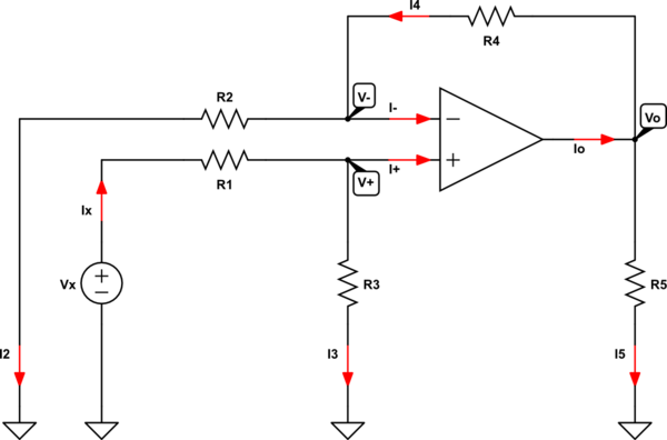
Well, we have the following circuit (and we assume an ideal model of an OPAMP):
schematic

simulate this circuit – Schematic created using CircuitLab

Using KCL, we can write:

$$ \begin{cases} \text{I}_4=\text{I}_-+\text{I}_2\\ \\ \text{I}_x=\text{I}_++\text{I}_3\\ \\ \text{I}_\text{o}=\text{I}_4+\text{I}_5 \end{cases}\tag1 $$

Using KVL, we can write:

$$ \begin{cases} \text{I}_x=\frac{\text{V}_x-\text{V}_+}{\text{R}_1}\\ \\ \text{I}_2=\frac{\text{V}_--0}{\text{R}_2}\\ \\ \text{I}_3=\frac{\text{V}_+-0}{\text{R}_3}\\ \\ \text{I}_4=\frac{\text{V}_\text{o}-\text{V}_-}{\text{R}_4}\\ \\ \text{I}_5=\frac{\text{V}_\text{o}-0}{\text{R}_5}\\ \\ \end{cases}\tag2 $$

Notice: in the ideal OPAMP circuit we assume that \$\text{I}_+=\text{I}_-=0\$ and \$\text{V}_+=\text{V}_-\$.

Now, the gain is defined by:

$$\text{G}:=\frac{\text{V}_\text{o}}{\text{V}_x}\tag3$$

We can find an expression for the output voltage \$\text{V}_\text{o}\$, by solving the systems of equations:

$$\text{V}_\text{o}=\frac{\text{V}_x\text{R}_3\left(\text{R}_2+\text{R}_4\right)}{\text{R}_2\left(\text{R}_1+\text{R}_3\right)}\tag4$$

So, we get:

$$\text{G}=\frac{1}{\text{V}_x}\cdot\frac{\text{V}_x\text{R}_3\left(\text{R}_2+\text{R}_4\right)}{\text{R}_2\left(\text{R}_1+\text{R}_3\right)}=\frac{\text{R}_3\left(\text{R}_2+\text{R}_4\right)}{\text{R}_2\left(\text{R}_1+\text{R}_3\right)}\tag5$$

In your case we get:

$$\text{G}=\frac{68000\cdot\left(30000+63000\right)}{30000\cdot\left(12000+68000\right)}=\frac{527}{200}=2.635\tag6$$


Solving it, in general, gives (notice that \$\text{V}_+=\text{V}_-=\text{V}_\text{p}\$:

enter image description here

In your case (using your values):

enter image description here

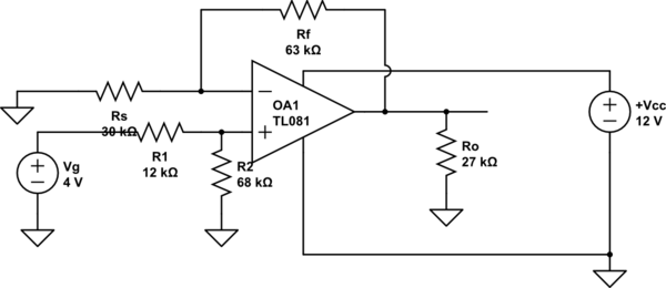
I checked my solution using LTspice and I got it right.
\$\endgroup\$
11
  • 1
    \$\begingroup\$ Wow! Hard work! \$\endgroup\$
    – Transistor
    Commented Jan 11, 2020 at 13:31
  • \$\begingroup\$ @Transistor Thanks, just a few minutes of thinking. \$\endgroup\$ Commented Jan 11, 2020 at 13:34
  • \$\begingroup\$ You need to verify your calculation and the formula you use. Check again. There are mistakes there. \$\endgroup\$ Commented Jan 11, 2020 at 15:18
  • \$\begingroup\$ @AirCraftLover I did using LTspice. Look at the bottem of my answer \$\endgroup\$ Commented Jan 11, 2020 at 15:19
  • \$\begingroup\$ See the answer from @g36 below the question's body. It is the correct formula to calculate. Moreover, my concern in my question is something like asking tutorial How do I do calculation using CircuitLab rather than asking how to calculate. \$\endgroup\$ Commented Jan 11, 2020 at 15:22

Your Answer

By clicking “Post Your Answer”, you agree to our terms of service and acknowledge you have read our privacy policy.

Not the answer you're looking for? Browse other questions tagged or ask your own question.