0
\$\begingroup\$

Knowing that:

$$V_{BE(on)}=0.7V, β=100, V_A=100V$$

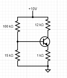
I'd like to find the collector current of the following circuit:

enter image description here

It seems I will have to use the fact that the base emitter voltage is 0.7 volts but I have no idea how to do this. Using the equations for the collector current in the forward active region, saturation current Is is required, which we don't have in this case.

Another idea, is to try and find the voltage around the 1KΩ resistor which can be found easily if we know the voltage around the 15KΩ resistor. If we assume that the base current is very small,the two resistors on the left branch form a voltage divider and calculations become very easy. However, I want precise numbers so I can't make this assumption.

Maybe I could find the input resistance seen from the base and that would allow me to calculate the base voltage precisely. I know the Rin seen from the base but only for small signal models. I don't think I'm allowed to use it here, since we don't have "small signals".

$$R_{inB}=rπ+(β+1)R_E$$

\$\endgroup\$
2
  • 1
    \$\begingroup\$ You want to find the DC current? If so try read this electronics.stackexchange.com/questions/471906/… and this \$\endgroup\$
    – G36
    Commented Jan 11, 2020 at 12:43
  • \$\begingroup\$ You can make precision calculations but, unless you take many more parameters into account your precision answer won’t compare with real life very precisely. \$\endgroup\$
    – Andy aka
    Commented Jan 11, 2020 at 12:48

1 Answer 1

4
\$\begingroup\$

You say you want precise numbers (I think you mean accurate) and you are not willing to assume that \$I_B \ll I_C\$. At this point you should use a good SPICE simulator instead of hand calculations. However, the model parameters for the transistor will also be approximations so those results won't be 100% accurate either.

You could build the circuit and test it, as long as all of your test equipment is under calibration and traceable to NIST. However, there is a great deal of variation between transistors of the same part number, so your results will only be valid for that one single transistor and those particular four resistors. If you build another copy of the circuit you will get different results.

We are engineers here. Make the assumption about \$I_B\$ and get along with the project.

\$\endgroup\$

Your Answer

By clicking “Post Your Answer”, you agree to our terms of service and acknowledge you have read our privacy policy.

Not the answer you're looking for? Browse other questions tagged or ask your own question.