3
\$\begingroup\$

I'm looking at the schematic for the MC1460 voltage regulator. At the top it has three current mirrors, each with an NPN-PNP pair. Is there a name for that transistor structure? These pairs look like Sziklai pairs except there is an emitter-base connection rather than an emitter-collector connection, and four connections in total.

I've experimented with the circuit in LTspice, but I'm not sure why they implemented it this way. It's more complex than other current mirrors I've looked at. The mirrored currents are sourced by the PNP collectors, but I'm not sure what current is controlling the mirror. There's a Zener-controlled current going to the bases of the NPN transistor, and a second current going through resistors to the emitter-collector connection. It appears that both of these currents affect the output. Any suggestions on how this current mirror works?

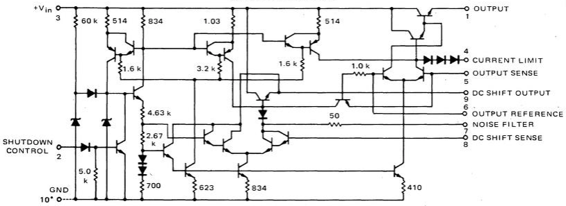
Schematic of the MC1460 voltage regulator

\$\endgroup\$
7
  • 1
    \$\begingroup\$ WHich part of datasheet did you not understand about 4 quadrant multiplier? \$\endgroup\$
    – D.A.S.
    Commented Jan 13, 2020 at 4:23
  • 1
    \$\begingroup\$ @TonyStewartSunnyskyguyEE75 I don't understand your comment. This is a voltage regulator, not a 4 quadrant multiplier. \$\endgroup\$ Commented Jan 13, 2020 at 4:39
  • \$\begingroup\$ @KenShirriff That's got to be an old IC. They are using NPNs like it's all they have on hand and PNPs like gold. It would be interesting to see the rubylith for this IC. Must be circa 1971 +/- a year or two, I'd guess. One of the problems back then was that resistors would be consistent, one to another, but their absolute values might be twice or half the intended values ... one IC to another IC. So this design compensates by designing a circuit that depends on ratios and not absolute values. What did you want to know, though? I don't the name. But I see what it does. How it works is easy. \$\endgroup\$
    – jonk
    Commented Jan 13, 2020 at 5:08
  • 1
    \$\begingroup\$ @jonk Yes, it's a very old IC (1968). I'm looking at it for historical reasons, not because I plan to use it :-) The link in my question includes a layout image if you're interested. What I really want to know is why they didn't use a "normal" current mirror, and how this one works. My theory is that the current through the 834Ω resistor sets the base one diode drop below Vin. The 623Ω resistor controls the second current, split between the 1.6k and 3.2k resistors, making the PNP bases equal. This forces equal voltages across the 514Ω and 1.03k resistors, generating the desired currents. \$\endgroup\$ Commented Jan 13, 2020 at 5:24
  • 1
    \$\begingroup\$ @jonk At least a few years older than that, it was already in hobby magazines in 1969 May (Ham Radio Magazine) so maybe '67 or '68. Not a rubylith, but the layout looked like this \$\endgroup\$ Commented Jan 13, 2020 at 5:31

1 Answer 1

6
\$\begingroup\$

I think they are just composite NPN - (lateral) PNP.

In the day (ca. 1970), the only real PNP transistors they could make with that bipolar process would have been lateral PNP types with miserably low hFE (maybe 1/10 of the NPNs).

This contemporary patent has some similar structures eg. Fig 5.

\$\endgroup\$
7
  • \$\begingroup\$ There's a lot more to say about this structure. I'm sure you know that. Here, resistor ratios appear to dominate the design. \$\endgroup\$
    – jonk
    Commented Jan 13, 2020 at 5:39
  • \$\begingroup\$ @jonk Absolutely. The whole thing is simple enough that you could do one of your very thorough analyses for sure. I'm not going to do anything more here. \$\endgroup\$ Commented Jan 13, 2020 at 5:43
  • 2
    \$\begingroup\$ Got it. If the OP is isn't interested in more then your answer is sufficient. Otherwise, a mere hobbyist with not even a DC class under his belt can provide more as needed. \$\endgroup\$
    – jonk
    Commented Jan 13, 2020 at 5:46
  • \$\begingroup\$ As well as the pair name, I wanted to highlight the PNP characteristics since the OP is doing LTspice simulations and a typical discrete PNP model is going to be way better than the real thing was. \$\endgroup\$ Commented Jan 13, 2020 at 5:51
  • \$\begingroup\$ I considered the Sziklai pair, but that has the NPN transistor pulling the base low, while in the circuit I'm looking at, the NPN transistor pulls the base high. Is it a Sziklai pair either way? \$\endgroup\$ Commented Jan 13, 2020 at 5:59

Your Answer

By clicking “Post Your Answer”, you agree to our terms of service and acknowledge you have read our privacy policy.

Not the answer you're looking for? Browse other questions tagged or ask your own question.