2
\$\begingroup\$

Background:

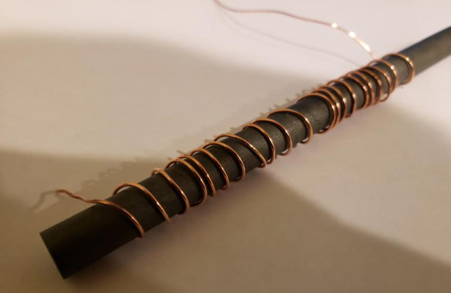
I bought a material 77 ferrite rod for a homemade inductor. The core was 0.5" in diameter and 7.5" long with a claimed initial permeability of 2000.

When I recieved it, I tested it out using 18 AWG wire that I wrapped around the ferrite core for the entire length. Granted, the windings were not perfect and had some gaps between parts of the wire and the ferrite core (probably 1 cm max),

Upon testing the inductor with my LCR meter, I measured a mere 0.04 mH.

QUESTION:

How come my inductor isn't exhibiting a relative permeability of 2000?

Here are a few pictures of my set up:

enter image description here

enter image description here

enter image description here

\$\endgroup\$
1
  • \$\begingroup\$ Joshua, if you built a long inductor that was 100's of meters long, the only really important parameter would be the number of turns per unit distance because turns "a long way, away" don't impact the field "over here." Finally, the permeability isn't important for something like this, because you have a 7.5" "air gap", one end to the other, and that completely dominates your magnetic path length. The result is \$L\approx \mu_0\,\left(\frac{N}{D}\right)^2\,A\,L_m\$. \$\frac{N}{D}\$ is the turns per unit length and \$L_m\$ is the magnetic path length (distance from one end to the other end.) \$\endgroup\$
    – jonk
    Commented Jan 18, 2020 at 18:09

2 Answers 2

1
\$\begingroup\$

You can find some calculators to allow you to approximate the inductance of coil wrapped on an open rod. If I plug your numbers into this one, I find 15 turns should be sufficient to yield 40uH with your stated dimensions (it won't let me spread the turns out as much as yours).

enter image description here

There is a link in the calculator to the equations they've implemented and I suggest you study the equations rather than trusting this (or any other) online calculator.

The inductance is much less than it would be with a closed magnetic path because the permeability of air is 1/2000 that of your rod.

A rather thorough treatment of how the effective Al varies with parameters can be had in this document.

\$\endgroup\$
1
\$\begingroup\$

The relative permeability of the core may indeed be 2000 but, the magnetism also flows through the air from one end of the rod to the other end and, this massively reduces the effective permeability of the whole inductor to a value that is closer to air.

The graph below is taken from a document entitled “Investigation on an Effective Magnetic Permeability of the Rod-Shaped Ferrites” from this source: -

enter image description here

So, with your length to diameter ratio of 15, the graph suggests the effective permeability to be around 50. The other down side to your coil construction is the spacing between consecutive turns; to maximise inductance you would wind them as close to each other turn as you can, even layering to get the turns closer. So, I would estimate that your effective permeability might be as low as 30.

Inductors, in the main, have closed magnetic cores with or without a small air gap. The air gap can be used to stabilise the inductance against temperature variations and also improve the current handling capabilities.

Your inductor construction would be fine for receiving the magnetic field in an EM transmission because it will concentrate the incident magnetism and give a much improved radio signal but, as a pure inductor it will have poor inductance.

Maybe if you could explain what you were trying to design I might be able to offer some suggestions?

\$\endgroup\$
4
  • \$\begingroup\$ Since I'm planning to apply 15 kV to the inductor, would layering the coils/putting them in contact with each other be problematic? \$\endgroup\$
    – user154046
    Commented Jan 18, 2020 at 0:14
  • \$\begingroup\$ Yes, certainly it would without the right insulation layers. But, you ought to explain your objectives even more now that you have revealed the high voltage requirements. \$\endgroup\$
    – Andy aka
    Commented Jan 18, 2020 at 0:30
  • \$\begingroup\$ I need a 0.625 mH inductor for a hard tube modulator system I'm making. The system provides 10 uS pulses at a frequency of 10 Hz. The switching device for the PFN in a thyratron (also governs the 10 Hz frequency). The capacitor bank has a capacitance of 0.0444... uF. The capacitors are charged by 10 kV and 30 mA from a steady-state source (15 kV is just the peak voltage). The load is a grounded ionization/plasma chamber. Impedance of the plasma chamber is unknown and fluctuates strongly. Would you happen to have any tips as to how I could make a good 0.625 mH inductor? \$\endgroup\$
    – user154046
    Commented Jan 18, 2020 at 0:39
  • \$\begingroup\$ A circuit diagram would be more meaningful to me as would peak inductor current and maximum instantaneous voltage it might see. \$\endgroup\$
    – Andy aka
    Commented Jan 18, 2020 at 10:25

Your Answer

By clicking “Post Your Answer”, you agree to our terms of service and acknowledge you have read our privacy policy.