I would like to better understand how a PFC controller works, especially PFC which work in CCM mode. I found the following documentation from International Rectifier: https://www.infineon.com/dgdl/an-1077.pdf?fileId=5546d462533600a40153559563801007 which deals with the mechanism of a PFC converter. The mechanism is described at page 4: "One Cycle Control for PFC".
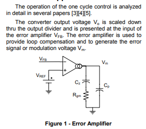
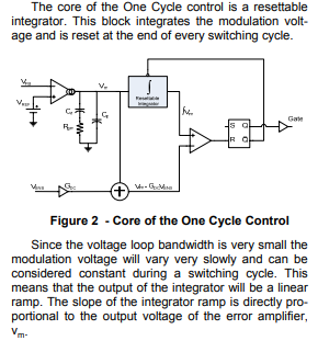
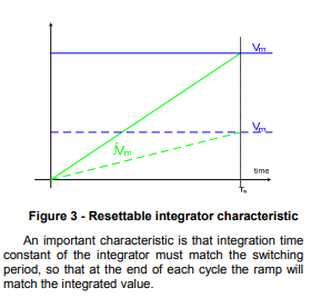
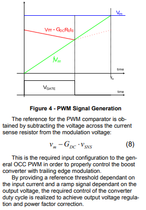
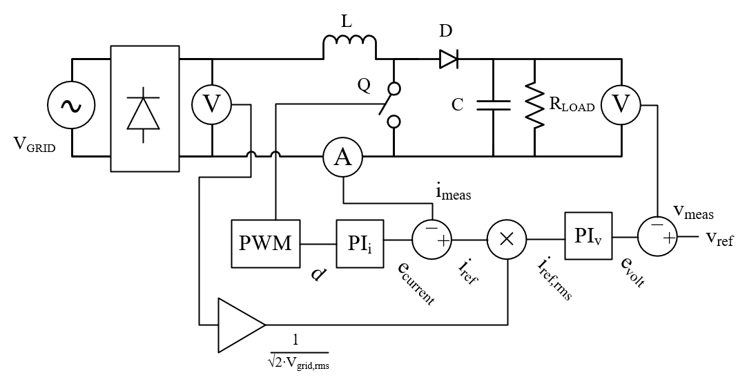
Here is what is described:
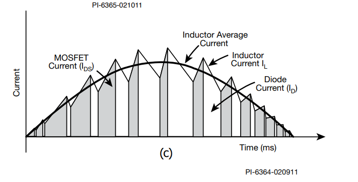
I know that the result duty cycle should look like to this:
What I understood: The main goal of a PFC is to put the input current in phase with the input voltage. In order to do this, if Vin (rectified) increases, the total variation of Iin (Ioff + Ion) across the inductor during the switching period must be superior to 0 in order to increase. It means that the Ion variation must be superior to Ioff variation. And inversely if Vin (rectified) decrease. Besides, the voltage output must be regulated to an output which is constant! So if Vin increases, we have to reduce the duty cycle in order to transfer less energy to the load and inversely when the input voltage decrease. This is exactly what we see in the above waveforms.
What I did not understand is how the controller works to do what we see on the above waveforms.
Suppose Pout is constant over the time. If Vin decreases, the energy transferred to the load decreases as the variation of the current across the inductor is lower, the the output voltage decreases, so the error amplifier voltage increases, it means that the slope of the integrated error amplifier voltage increase, then if Pout is constant as Vout is lower than previously, Iout which is proportional to Isense increases. So the slope of "-GdcRsIsense" (there is a minus) will increase, and it will tends to decrease the duty cycle where as we want to transfer more energy to the output in order to have a constant output voltage? Where is my error?
Thank you very much!

