0
\$\begingroup\$

The aim is to make a temperature control circuit using an Arduino Uno as a controller, an LM35 sensor as feedback to measure the actual temperature, a TIP31C transistor as actuator to control the power dissipated (heat.) I have a 12V,1A power supply.

Note: The transistor and sensor are near to each other.

I know that the Arduino Uno should send PWM through a resistor to the base of transistor, but what about collector and emitter?

Should I put 12V to the collector and ground to the emitter? But that would mean a short circuit.

\$\endgroup\$
3
  • 1
    \$\begingroup\$ Your post would be a bit more easily read if you capitalised sentences, part numbers, brand names and electrical symbols properly. If English is not your first language then add that into your user profile so we can help you out. Use a power resistor as the heater rather than the transistor and that way you can switch the resistor on and off using the transistor which when fully off (zero power dissipation in it) and when fully on (very low dissipation in it) as the voltage drop across it will be so low. \$\endgroup\$
    – Transistor
    Commented Jan 18, 2020 at 22:33
  • \$\begingroup\$ Define mass of all targets being heated and temperature difference above ambient. Also indicate acceptable overshoot or rate of change of T. THis is probably just a linear control system. \$\endgroup\$
    – D.A.S.
    Commented Jan 18, 2020 at 22:49
  • \$\begingroup\$ Do you realize you have unspecified requirements? Or do you just want to regulate the TIP temp? \$\endgroup\$
    – D.A.S.
    Commented Jan 19, 2020 at 3:11

2 Answers 2

1
\$\begingroup\$

You can use a transistor as a heater, however you would be better off to add at least one resistor to control the collector current. Given that, you might want to use the resistor itself as the heater and drive the BJT or MOSFET fully on to minimize the power dissipation in the switching device.

Dale makes suitable chassis-mount wire-wound resistors, and you can find other suppliers with similar products. Photo from Digikey:
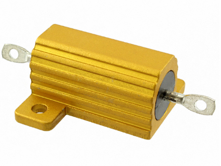
enter image description here

If you still want to use the transistor for some reason, you can make the transistor into a current sink and connect the collector to a fixed voltage, so power dissipation is more-or-less fixed when 'on' Look elsewhere here for ideas on how to do that. The easiest way would be to drive the base to +5 and add a resistor in the emitter so you'd get a current of 4.3V/Re and a transistor power dissipation of P=(12V-4.3V)*4.3V/Re. That doesn't count the power dissipated by the emitter resistor.

If you reduce the drop on the emitter resistor to something less, like say 100mV you can put more of the dissipation in the transistor, but that requires a more complex circuit (we'd probably use an op-amp). An intermediate solution would have 600mV drop in an emitter resistor and use a BJT to throttle current to the base or voltage to the gate of a power transistor.

\$\endgroup\$
0
\$\begingroup\$

The current trough a transistor is poorly controlled by the base current. Is is better controlled by the base emitter voltage. However, that formula also calls for millivolt control ( as well as knowledge of the temperature, which you know). Given these drawbacks, the very best solution may be to use some sort of current sensing...like an emitter resistor.

I suggest you connect your transistor as an emitter follower. The current through the transistor is then well controlled by the input voltage. Choose an emitter resistor as large as possible to get good control...but, of course, the size of this resistor sets the maximum current, so there is a trade off here. You will likely need a power resistor for this.

\$\endgroup\$

Your Answer

By clicking “Post Your Answer”, you agree to our terms of service and acknowledge you have read our privacy policy.

Not the answer you're looking for? Browse other questions tagged or ask your own question.