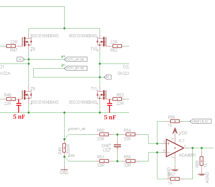
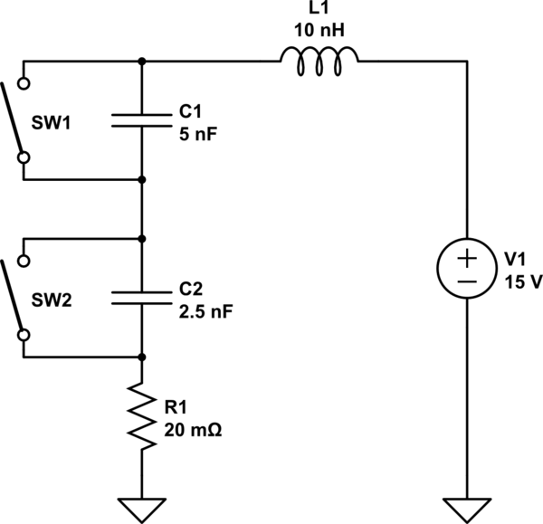
I'm trying to build a stepper-motor driver. Each windig is driven as shown:
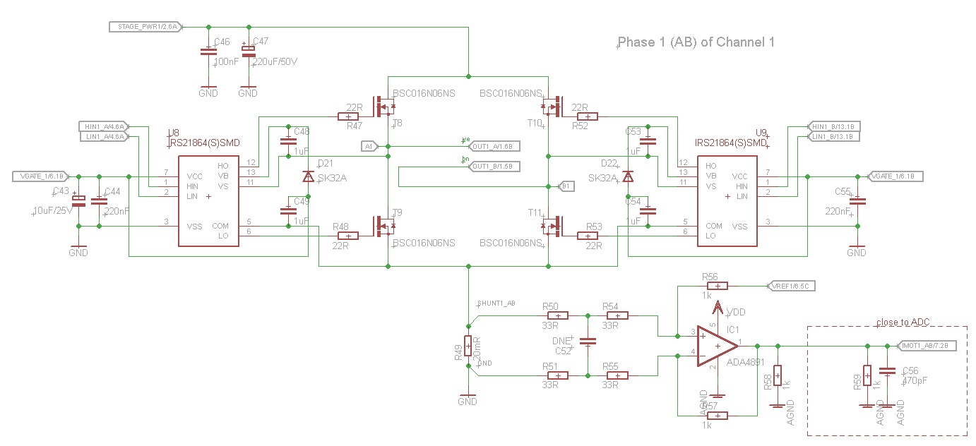
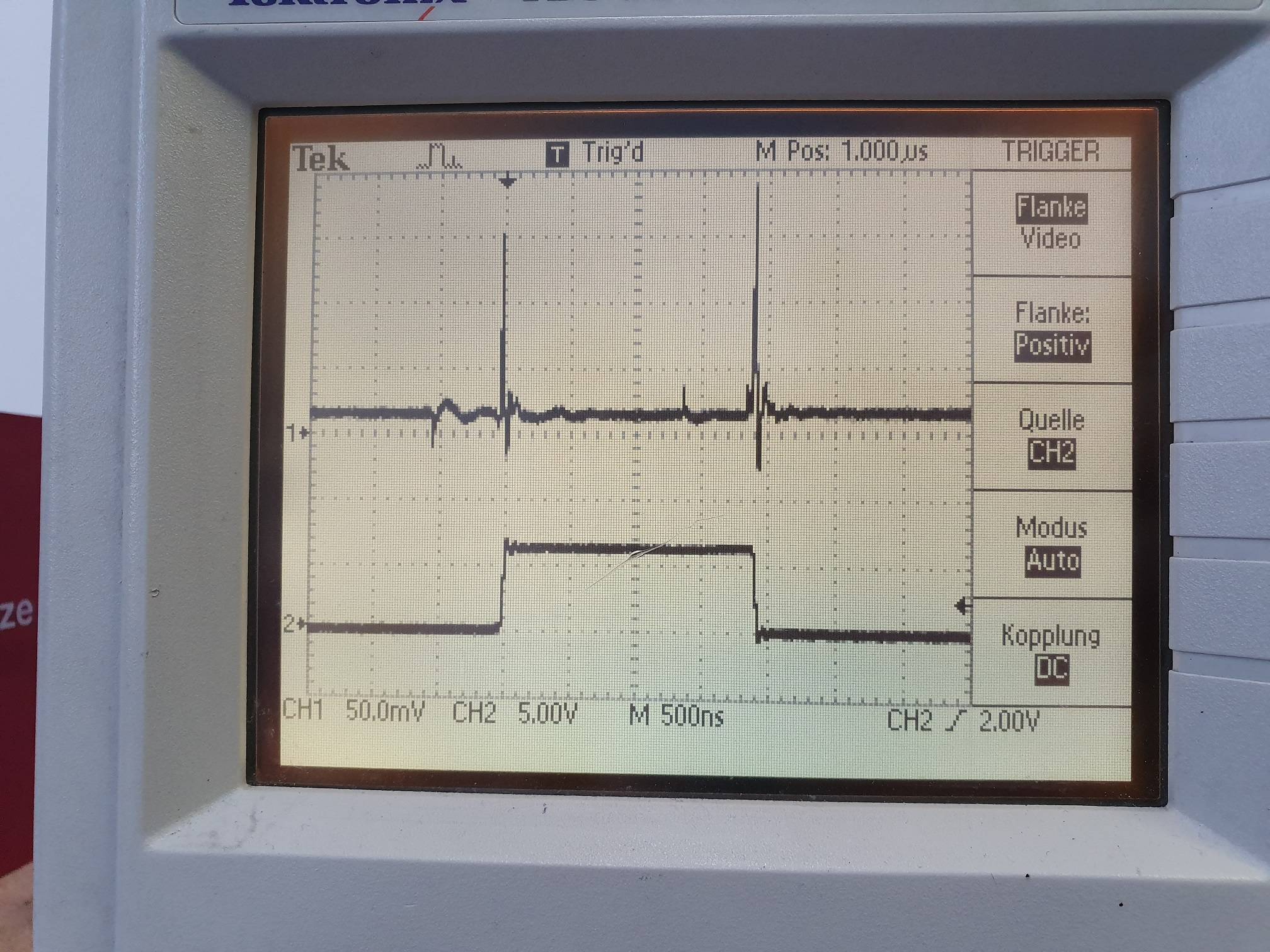
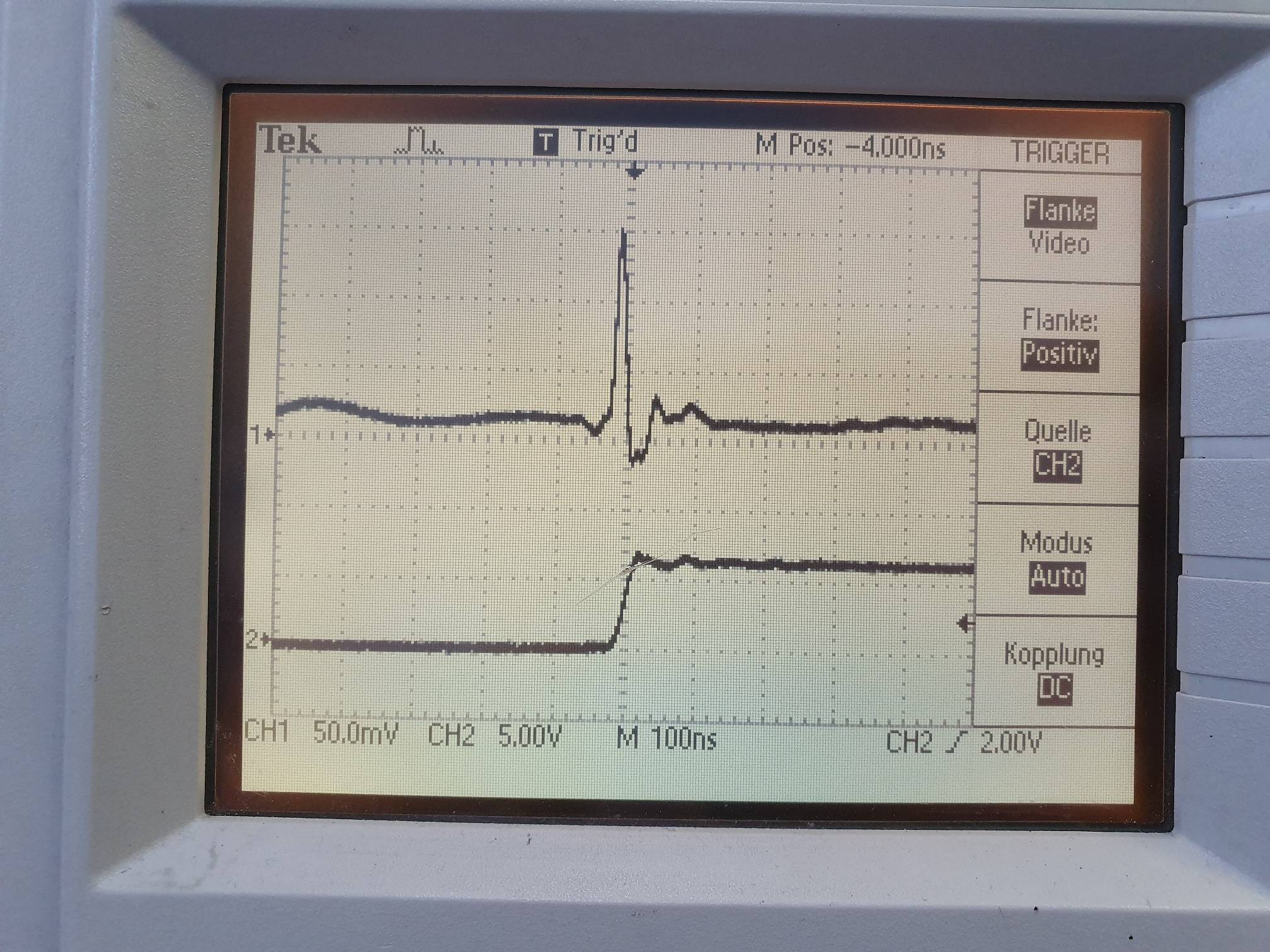
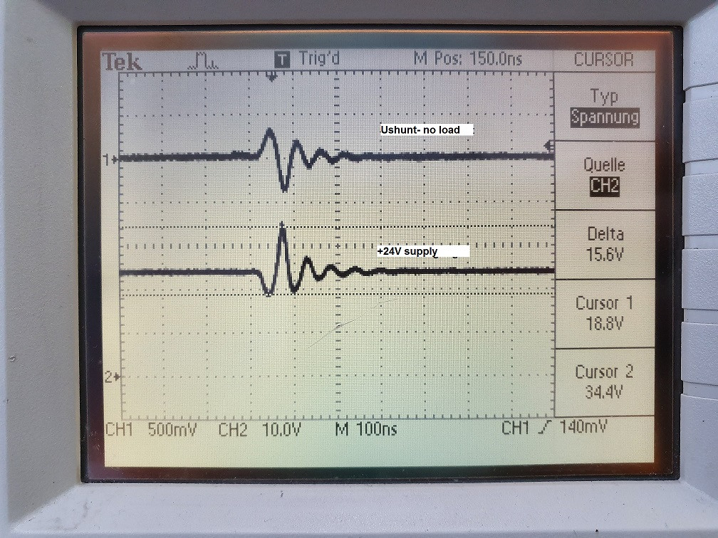
at the moment, im feeding this with PWNM signals of constant duty cycle, just to see how everything response. (PWMs are complementary to drive current in only one direcion) So i'm not using the OPAMP and MCU to measure any currents. What i see is that when a Mosfet gets turned on or off i see a spike over the shunt resistor, even with no load attached.
CH1 = voltage over shunt resistor CH2 = voltage at switching node
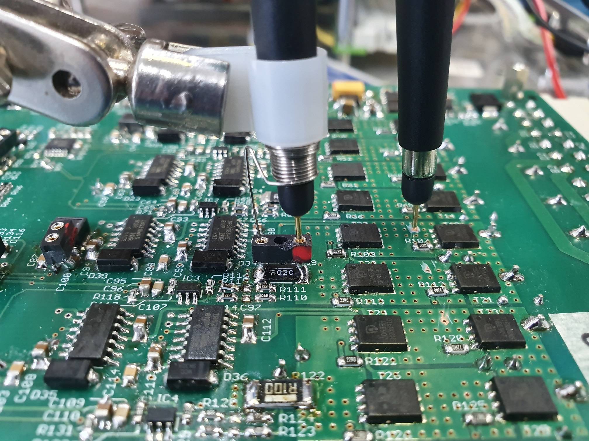
output voltage looks ok, same under load (testet with up to 3A). But im not shure where these spikes are comming from. I used a Ground-clip to measure this.
Any idea how i can get rid of this? Or is there anythin obvios wrong with my schematic. My current prototype uses a 4-Layer pcb with an (almost) solid GND-plane and seperate supply-planes under each H-bridge.
Update:
Dead-time of PWM signal is 460ns. I changed the gate resistors to 10R to allow for faster rise/fall of each gate voltage. but no improvment on the shunt signal
Output signal of the gate driver:
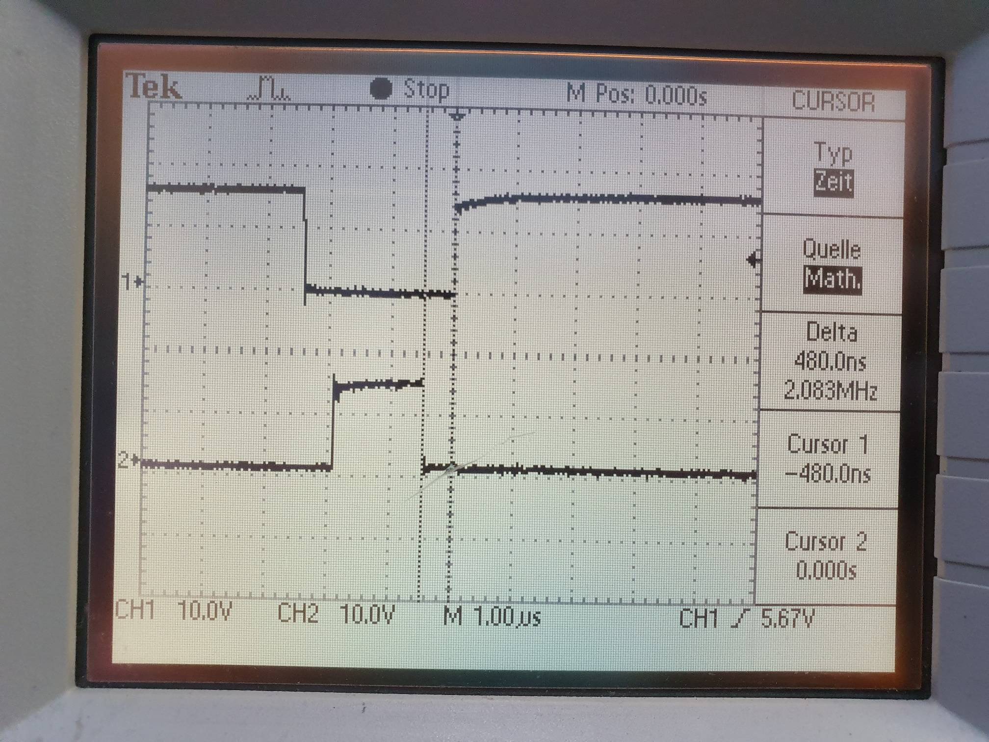 Gate voltages with RG = 22R
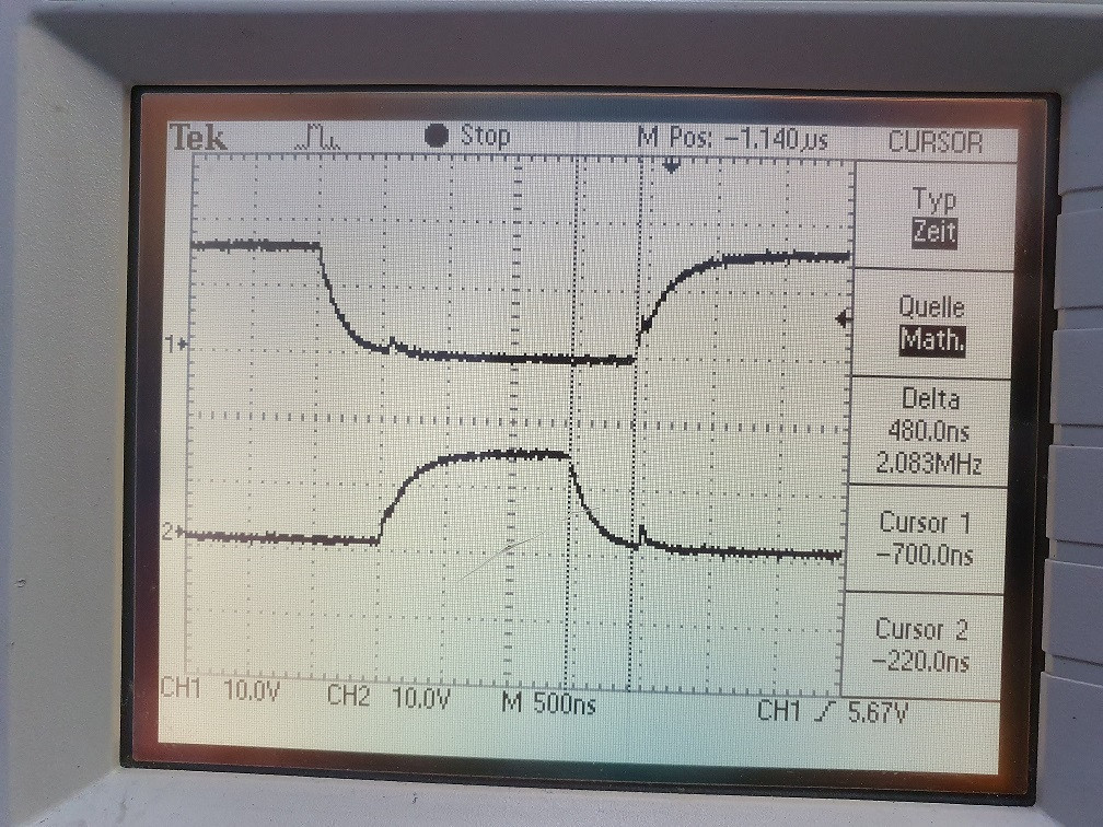 Gate voltages with RG = 10R
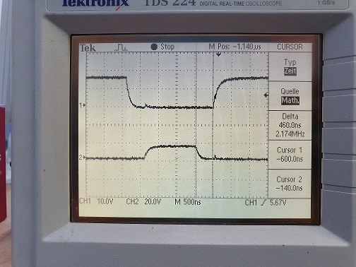 Better Measurement of gate voltages, might this peak be the problem?
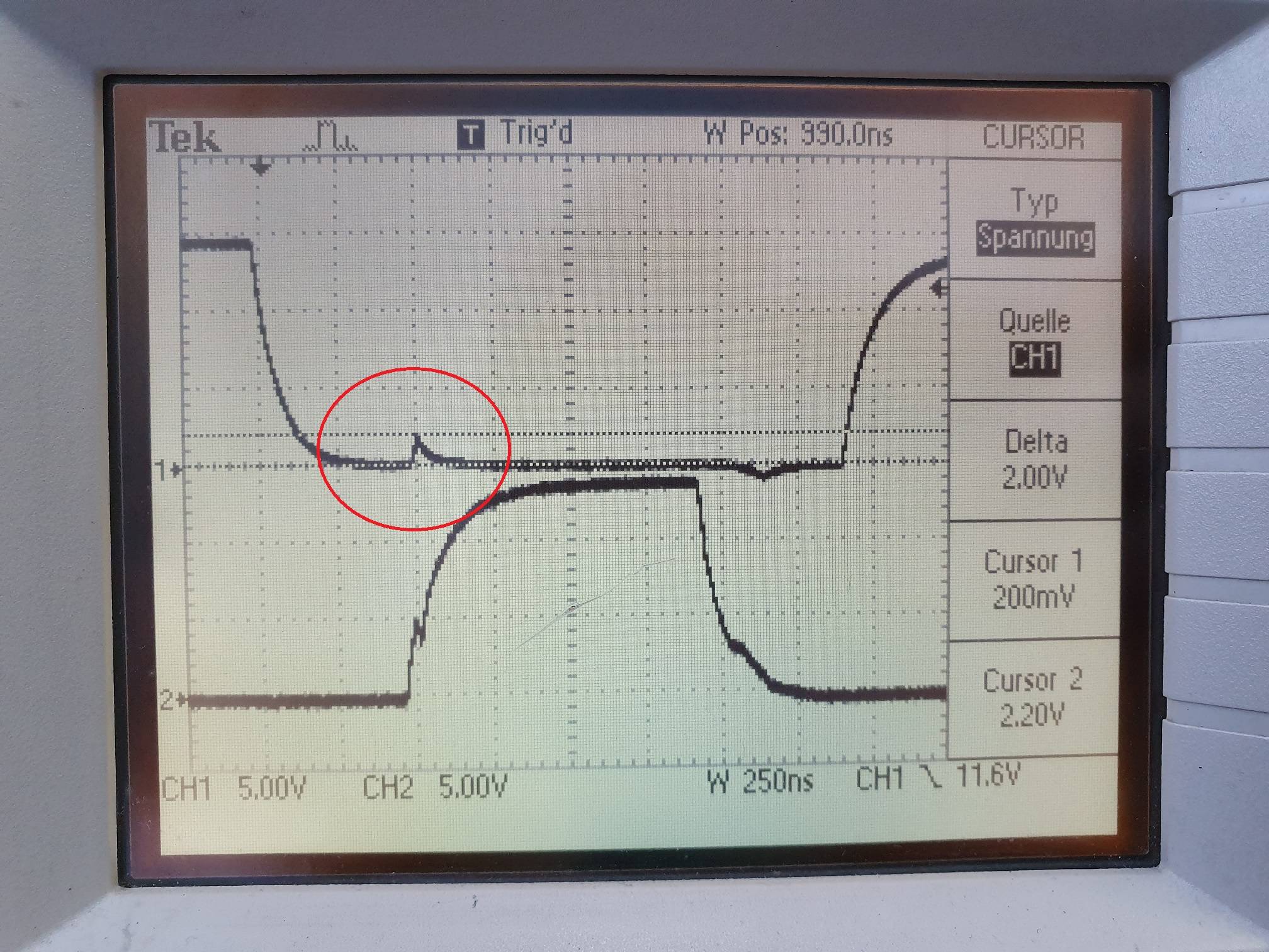
Update 2:
i've been testing and probing around to see if i can narrow it down. Wiring C49 and C54 directly to GND (as mentioned by peufeu) improved the signal over all, but it did not affect the spikes. But the signal is much cleaner right befor the spike, during dead time.
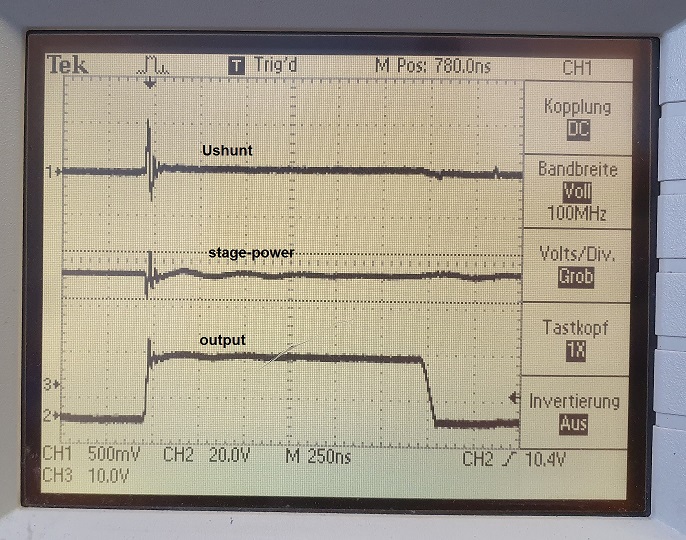
I found out that this Spike/swing is also present on the supply voltage. I changed C47 to 1000uF and still the supply voltage swings about +/-5V and more. Under no load, and there is no current drawn form the power supply. Wouldn't i take quite some current to cause such fast voltage change over an Elko? The swing on the supply voltage looks basically like the one over the shunt, but inverted.

