0
\$\begingroup\$

In a circuit with a resistor parallel to a diode/resistor, will the voltage across both resistors be the supply minus the 2v drop of the LED?

Meaning you would calculate it still by using resistors in parallel: 1 ÷( 1/r1 + 1/r2). And then use supply minus 2v ÷ R to get the total current? Is this correct?

I am trying to teach myself electronics and find it very hard to find definitive answers on the things I am trying to learn. Therefore I am wanting to just try get confirmation on a question if I can.

I get confused as in a parallel split the voltage is unchanged on each wire, only current is halved. But since one lane has a voltage drop I initially assumed they would rejoin with different voltages which wouldn't make sense. And I have learnt that if there is 2 diodes it would only activate the one with the lowest forward biasing voltage and the other would stay off. .
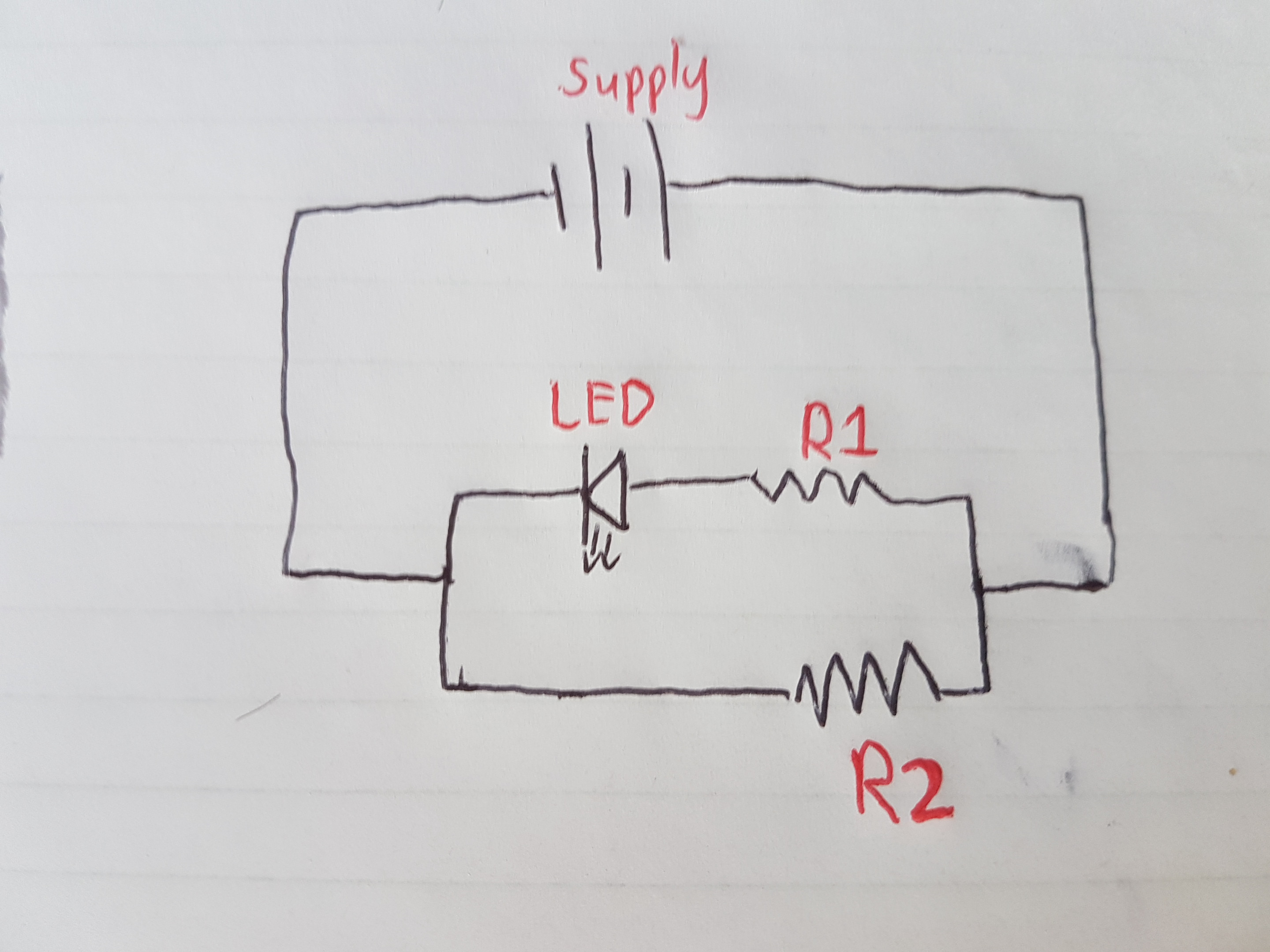
circuit

I have done a few tests and found that seem to imply this is the case but none seem to definitively say it. If someone would be and to assist in confirming that this is the case that would be appreciated.

I have been learning about diodes and LEDs but keep running into problems that tutorials haven't discussed so it's tricky to find all the information. Apologies if I'm not posting correctly this is my first post. Also I know there is a circuit editor but I can't seem to see it in mobile. Thank you

EDIT: Schematic for a comment.
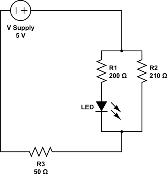
schematic

simulate this circuit – Schematic created using CircuitLab

\$\endgroup\$
1
  • \$\begingroup\$ the current spits, but is not necessarily halved ... the ratio of current between the two resitors is dependent on the ratio of the resistances .... think of a river with an island in the middle ... if the island is exactly in the middle of the river, then equal amount of water flows on each side ... not so if the island is closer to one shore \$\endgroup\$
    – jsotola
    Commented Jan 26, 2020 at 2:28

2 Answers 2

0
\$\begingroup\$

will the voltage across both resistors be the supply minus the .7v drop of the LED?

No. You have drawn a nice schematics. The R2 resistor is direklty in parallel to the source voltage. So the voltage across the resistor will be same as the source voltage.

  1. Proceed in this way. R2 is directly in parallel with the source voltage. Hence the voltage has to be the same as source Voltage
  2. For R1, there are two components in series. The diode drop plus the drop across the resistor R1 has to be same as the supply voltage.
  3. The voltage across the diode depends on many factors one of which will be the supply voltage itself and the other will be the forward Voltage of the LED. (About 2.4 V upto 4 V depending on the type of the LED, but definitely not 0.7 V as in normal diodes).

If there are two sides in parallel, the diode with the lower forward Voltage drop turns on first there by keeping he voltage across the second diode too lower than the forward Voltage drop of the second diode. Hence the second diode will not turn on (completely).


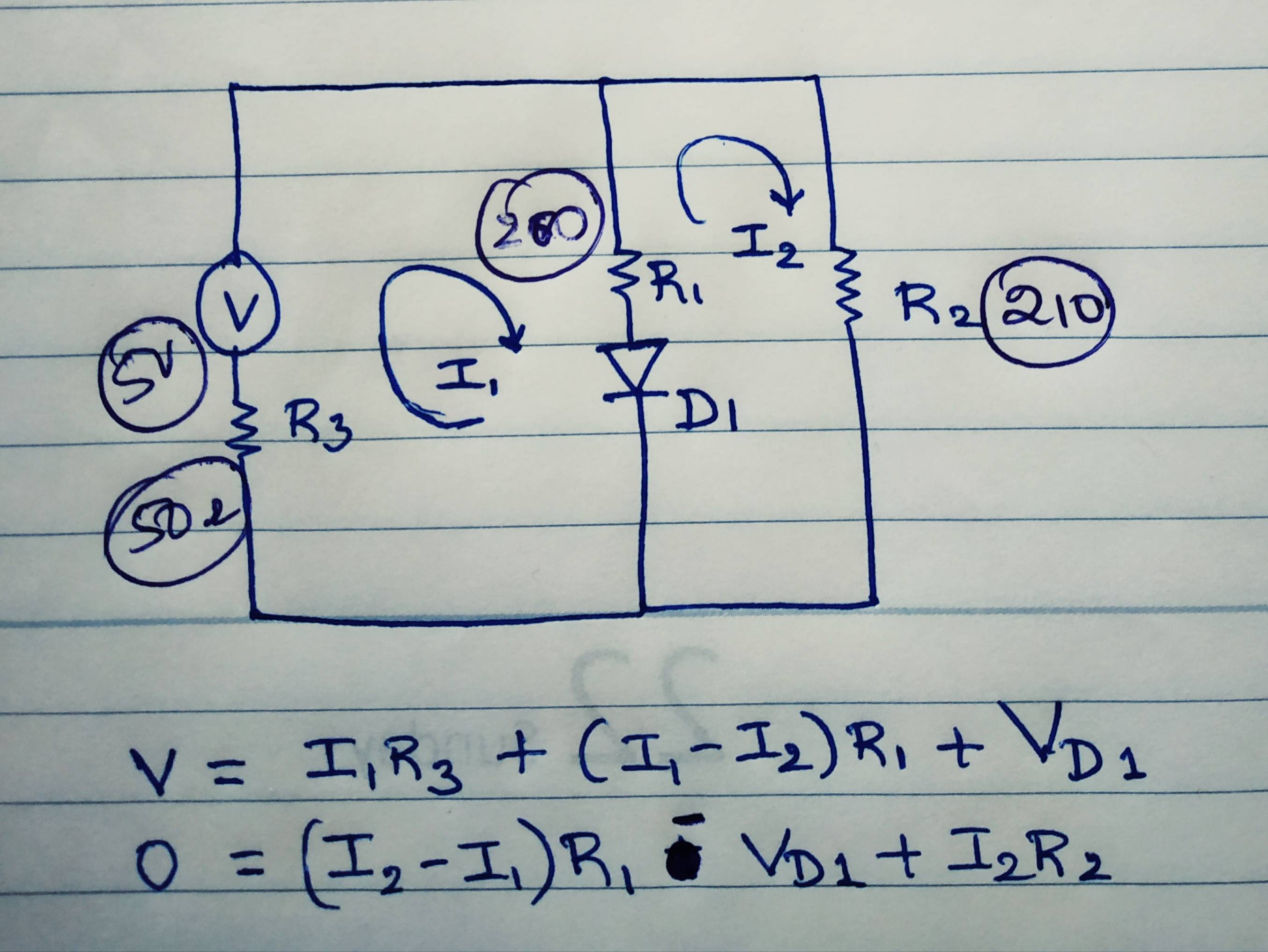
  • Start with the loop equations. Except I1 and I2 other parameters are constant and can be solved. I would approach the problem in this way.

enter image description here

\$\endgroup\$
12
  • \$\begingroup\$ Thank you for your in-depth reply. Sorry I made a mistake i meant minus 2v for the led I was just thinking of normal diodes. But how does that work with kerchoffs law? If say the supply is 5v and it's a red LED of 2V to forward bias. And let's say both resistors are 10 ohms. Wouldn't there be a voltage of supply - 2v across both resistors? As the 5v is Across the resistor and also the resistor and led? And both would need to use the 5v so the resultant is 0v back to ground. \$\endgroup\$
    – Ciribear
    Commented Jan 26, 2020 at 6:18
  • \$\begingroup\$ @Ciribear there are two branches. One branch is the series combination of R1 and LED. The second branch is R2 alone. Both branches are parallel to each other. They share common nodes. The voltage across both the branches is 5 V. First Branch had two components.. hence the LED will take its 2V and the remaining (3V) will be dropped across R1. The R2 will see full voltage as it is the only component in its branch \$\endgroup\$
    – User323693
    Commented Jan 26, 2020 at 6:28
  • \$\begingroup\$ @Ciribear R1 and R2 are not in parallel because they won't share same nodes \$\endgroup\$
    – User323693
    Commented Jan 26, 2020 at 6:34
  • \$\begingroup\$ Thank you I understand that. What happens if there is a resistor in series with that. Would you calculate the total current using supply minus 2v. And still calculate the total resistance of the parallel as 1 ÷ 1/r1 + 1/r2 (then plus the 3rd R)...... Then divide both? \$\endgroup\$
    – Ciribear
    Commented Jan 26, 2020 at 7:04
  • \$\begingroup\$ @Ciribear resistor in series with that .. with which component? R1? \$\endgroup\$
    – User323693
    Commented Jan 26, 2020 at 7:14
2
\$\begingroup\$

The voltage across R2 will be the supply voltage, as it is connected directly across the supply. R1 and the LED will have no affect on the voltage across, or current through R2 (assuming the supply can provide sufficient current).

The voltage across R1 will be the supply voltage minus the forward voltage of the LED. The presence of R2 will not affect the current through R1 and the LED.

If you add an LED in series with R2, both LEDs will light, even if they have different forward voltages.

If you connect a second LED in parallel with the one shown, only the one with the lower forward voltage will light.

\$\endgroup\$
2
  • \$\begingroup\$ Thank you for your reply that makes sense. I think I was getting confused. But in the case of wanting to light a 2nd LED with R2 though you could would just have to make sure the resistors values took enough of the supply voltage on each lane to provide the forward voltage required for each LED though right? \$\endgroup\$
    – Ciribear
    Commented Jan 26, 2020 at 9:17
  • \$\begingroup\$ You should think of the resistor as controlling current through the LED, not as "taking enough of the supply voltage". The voltage across the resistor will depend on the current through it. \$\endgroup\$ Commented Jan 26, 2020 at 16:43

Your Answer

By clicking “Post Your Answer”, you agree to our terms of service and acknowledge you have read our privacy policy.

Not the answer you're looking for? Browse other questions tagged or ask your own question.