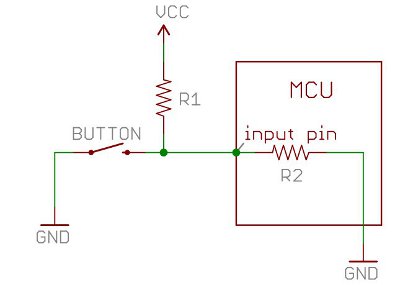
Here is the illustration for pull-up resistor, I am wondering if the button still can drain the input voltage to GND when the wire between button to MCU is very long which increases the impedence of wire to certain extent(Need determined, i.e. Wire impedence vs R1 and R2).
-
\$\begingroup\$ Yes. It will just be slower because of higher parasitic capacitance and inudctance. Also, you said wire between button and MCU which is a bit ambiguous because it is not clear if R1 is closer to the MCU or to the button. \$\endgroup\$– DKNguyenCommented Jan 27, 2020 at 4:39
-
\$\begingroup\$ @DKNguyen Thank you for answering, so is there a way to improve? To increase the speed for example? \$\endgroup\$– JeffsonCommented Jan 27, 2020 at 4:41
-
\$\begingroup\$ There are, but I doubt you need it. Remember, we are talking about human time scales for pushing and releasing a button versus electronic time scales. Mechanical switches bounce for several milliseconds when switched and electronics circuits tend to be fast enough to see each and every bounce. Can you even push and release a button faster than 100ms? \$\endgroup\$– DKNguyenCommented Jan 27, 2020 at 4:42
-
\$\begingroup\$ Uhm, okay, got it. Thanks again. \$\endgroup\$– JeffsonCommented Jan 27, 2020 at 4:44
-
1\$\begingroup\$ Don't forget to debounce your switch...probably in software judging from the way you wired it. \$\endgroup\$– DKNguyenCommented Jan 27, 2020 at 4:44
1 Answer
Assuming you have a common ground across the length of cable, the pull-up resistor should be placed on the far end as termination. Depending on the resistance(length) of the cable and the voltage levels, a significantly low value pull-up resistor could possibly keep the controller from detecting a low signal, but that is unlikely unless you are using a resistor of 1K or less, and those low values would be bad design anyhow.
As also suggested in the comments, you should have a small capacitor in place to lower transition jitter...
-
\$\begingroup\$ Good point about the termination. Never thought about it that way. Although you don't need to know anything about terminations to realize that the resistor should probably be closest to the pin that is doing the reading. \$\endgroup\$– DKNguyenCommented Jan 27, 2020 at 4:59
-
\$\begingroup\$ @DKNguyen - Exactly! While I have known that fact for 20 years, it just now occurred to me that a termination resistor could be analogous to a pull-up resistor. Oh the stupid obvious things that never hit me in the face in all these years... \$\endgroup\$– HitekCommented Jan 27, 2020 at 5:04
-
\$\begingroup\$ If it's long enough, you may also be sensitive to EMI. The lower the impedance on the line (primarily the pullup), the more the EMI will be mitigated. If you're in a normal RF environment and your signal is digital, it probably won't be much of an issue, but it may react to nearby transmitters. \$\endgroup\$ Commented Jan 27, 2020 at 14:52

