0
\$\begingroup\$

I need to send a signal from a Raspberry Pi 4 to a PC running software that listens on a COM port and I'm having some trouble understanding the necessary wiring.

Here is the documentation I have for how to communicate to the software through a DE-9 port: Description for how to control the software through a DB9 connection
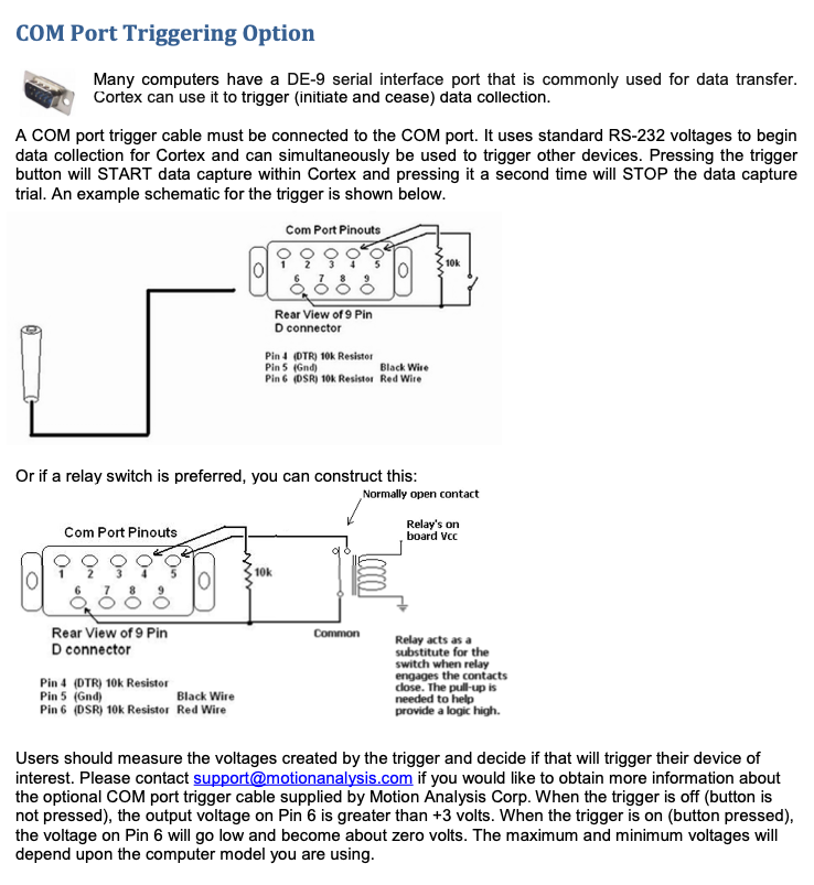
I have a DB9 breakout board: https://www.amazon.com/gp/product/B00WPBXDJC?pf_rd_p=ab873d20-a0ca-439b-ac45-cd78f07a84d8&pf_rd_r=Y5WXCRKKDNTY4GC84C4R

Am I able to use the built-in pull-up resistors on the Raspberry Pi 4? What wiring do I need to send the correct signal?

It sounds like I can keep the DB9 #6 pin high (3.3V) by connecting it directly to a Raspberry Pi GPIO port that has a pullup resistor (making sure to enable it in software). When I want to trigger the device, it sounds like I can set that pin LOW for a few milliseconds. Is that correct? Or, do I need additional setup?

If necessary, I also have a relay on-hand I can use: https://www.amazon.com/gp/product/B01M0E6SQM/ref=ppx_yo_dt_b_asin_title_o02_s00?ie=UTF8&psc=1

Thank you for any help you can provide - I'm a software guy and this electrical setup is pretty foreign to me!

\$\endgroup\$
4
  • \$\begingroup\$ Ok. Does the level shifter in the DB9 breakout board above help at all there? If not, what would you recommend I add to help with this? Thank you. \$\endgroup\$
    – Mike Buss
    Commented Jan 30, 2020 at 16:51
  • \$\begingroup\$ Also, in the documentation I linked it says the output voltage on pin just needs to be greater than +3 volts (and 0V to trigger). Does that affect your answer? \$\endgroup\$
    – Mike Buss
    Commented Jan 30, 2020 at 16:51
  • \$\begingroup\$ Mike, I'll withdraw my comment. I somehow missed the link to the converter completely, Sorry for being such an idiot! \$\endgroup\$
    – Oldfart
    Commented Jan 30, 2020 at 16:55
  • \$\begingroup\$ No problem! So, in that case, would connecting a GPIO from the Arduino (with the pullup enabled) directly to the #6 on the DB9 for triggering the system work? \$\endgroup\$
    – Mike Buss
    Commented Jan 30, 2020 at 16:59

3 Answers 3

1
\$\begingroup\$

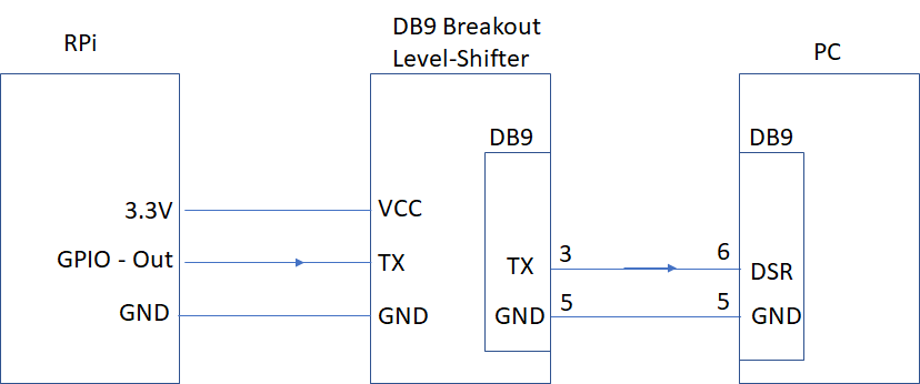
The DB9 breakout board that you specified is also a level-shifter. Supply it with 3.3V from the RPi. Then you can connect it directly to the RPi GPIO pins, no resistor is necessary.

The hardest part is getting the signal direction correct (3.3V and RS-232). TX & RX are only meaningful when the point of view is known.

The RS-232 DB9 cable may need to be a crossover cable, or you may need a null modem adapter.

Your level-shifter only has RX/TX, no handshake. You could substitute the signals and make a custom RS-232 cable.

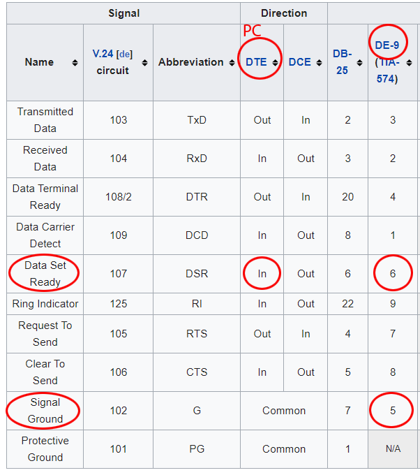
The custom PC software is apparently using Data-Set-Ready to trigger.

You have an RS232 level shifter, that may or may not have the handshake signals wired, I can't tell. But we can use the TX signal instead.

You will need to make a custom cable.

I can't be sure that I got the directions correct, it would help if I had full documentation for the level-shifter. Even with all the documentation, it is very easy to get confused, I often had to scope signals to get COM stuff working.

enter image description here

enter image description here

\$\endgroup\$
9
  • 1
    \$\begingroup\$ The instruction sheet I added above (see image) doesn't say that TX or RX need to be connected. I'm not sure I follow you when you're talking about TX and RX. Are you implying I need to use serial communication when the instructions say you're just supposed to apply 3V or 0V to the 6 pin to trigger the device? \$\endgroup\$
    – Mike Buss
    Commented Jan 30, 2020 at 17:23
  • 1
    \$\begingroup\$ The relevant line from above is "When the trigger is off, the output voltage on Pin 6 (DSR) is greater than +3V. When the trigger is on, the output volage on Pin 6 will go low and become about 0V". Can you clarify how TX, RX, and RS-232 communication with crossover cables come in to play? Thank you again for your help. \$\endgroup\$
    – Mike Buss
    Commented Jan 30, 2020 at 17:25
  • \$\begingroup\$ Sorry, I didn't read the fine print in the drawing, they are using the handshake signals, not RX/TX! You could still possibly substitute the signals, but it just got overly complicated. \$\endgroup\$
    – Mattman944
    Commented Jan 30, 2020 at 17:31
  • \$\begingroup\$ Ok, no problem. What would you recommend I do in that case? Is it just as simple as supplying 3.3V of power to Pin6 constantly (with internal pull-up?) and then setting it low temporarily when I want to trigger it? How best would I do that? Can the GPIO pin do it directly, or are you implying I need to use a relay where it connects or disconnects from VCC on the Raspberry Pi? \$\endgroup\$
    – Mike Buss
    Commented Jan 30, 2020 at 17:36
  • \$\begingroup\$ Use the relay as described in the vendor note. You will most likely need a transistor to drive the relay. Questions about RPi's driving relays are common here, you should be able to find one, or if not, ask further. \$\endgroup\$
    – Mattman944
    Commented Jan 30, 2020 at 17:38
0
\$\begingroup\$

Since modern PCs rarely have COM ports built into them anyway, it is best to use a USB to serial converter that uses 3.3V signal levels.

I use one from FTDI. https://www.amazon.com/Converter-Terminated-Galileo-BeagleBone-Minnowboard/dp/B06ZYPLFNB/

Or search for: USB to TTL Serial 3.3V

\$\endgroup\$
2
  • \$\begingroup\$ The PC we're using has a COM port on it for this purpose. We're controlling software that's fairly old, unfortunately. \$\endgroup\$
    – Mike Buss
    Commented Jan 30, 2020 at 16:57
  • \$\begingroup\$ I'll leave this answer since it may help others. \$\endgroup\$
    – Mattman944
    Commented Jan 30, 2020 at 17:19
0
\$\begingroup\$

I am not at all happy with how the relay is connected.

  1. I have no idea how much the voltage on the DSR/DTR lines is. According to the RS232 standard they can be between +/-3 to +/-25 Volts. That is a huge range
  2. Using them to switch a relay on and off is unlikely to work because:

    a. The signal is unlikely to have enough energy (current) to activate a relay.

    b. If it works for a tiny DC relay (e.g. reed relay) it may activated in both voltage directions. That is because a positive as well as a negative current will produce a magnetic field.

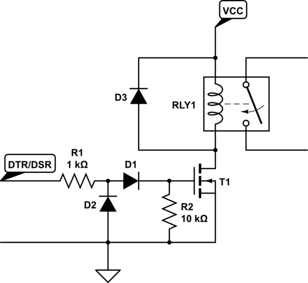
Here is a suggestion:

schematic

simulate this circuit – Schematic created using CircuitLab

VCC is an external supply, the voltage depends on your relay. You might use the 5V of the Raspberry-Pi.
D1 makes sure the FET is only activated if DSR/DTR is high.
D2 protect against negative voltage.
R1 is there to limit the current.
R2 is there to make sure the FET is off when there is no signal (It prevents the gate from floating).
D3 is the standard relay freewheel diode which is missing in your diagram at all. Without it your RS232 port may blow up.
You might have to play with the values of R1 and R2 (They might need to be larger). Also most FETs need at least 5V between the gate and drain to switch reliably so I would not like to try this with +/-3V.

Of course this has not been tried and if I made any mistakes I am sure somebody will jump to the occasion to point that out.

\$\endgroup\$
1
  • 2
    \$\begingroup\$ I think that you are seeing the question backwards. The OP is suggesting using the relay CONTACTS to switch the signals on the DB9. At no point does the OP suggest using the DB9 port to drive the relay coil. \$\endgroup\$ Commented Jan 31, 2020 at 3:17

Your Answer

By clicking “Post Your Answer”, you agree to our terms of service and acknowledge you have read our privacy policy.

Not the answer you're looking for? Browse other questions tagged or ask your own question.