2
\$\begingroup\$

I am searching for the cap load formula of C2 of the following circuit: Whole circuit
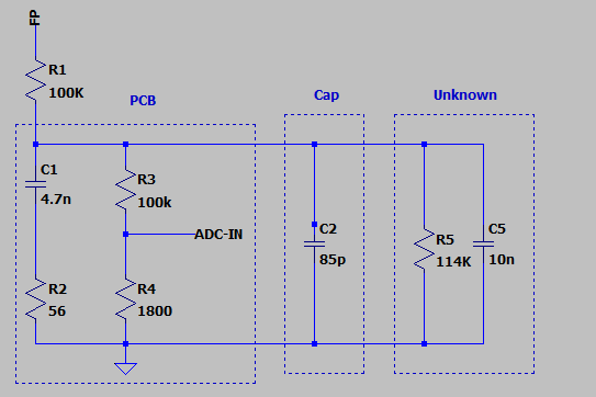
In the end I want to be able to determine the capacitance of C2 through the ADC-IN voltage.

The unknown part is a driver which sits besides the C2. The C5 is measured with and RLC meter after substracting the 4.7nF of C1. I applied 20VDC (30V/µs supply) and saw a voltage drop of 7V accross C2 - R5 is a pure assumption but seems to be accurate even with different FP voltages.

When i split the sections of the circuit, can I assume the following?:

I added R1 so the tau is in a measureable region.

C1 and R2 are a highpass filter which should send noise in the upper 100MHz against ground. - Can I ignore this part for the calculation?

R3 and R4 is a voltage divider for the ADC, this parallel to R5 is 53,85k Ohms.

I made the following assumpter:

At time = 0s and FP= 20V: Voltage is divided between R1 and (R3+R4)//R5 and the C1 and C5 start to load against 7V (resulting from the voltage divider).

I assume that R1 is my load resistor and I can ignore the R2-R5 for loading. So I have a capacitance of 10,085nF and after 1 tau (R1*(C2+C5)) I should be at 4,41V (63%)?

When I look at the graph measured parallel C2 i get 4nF: C2 Measurement
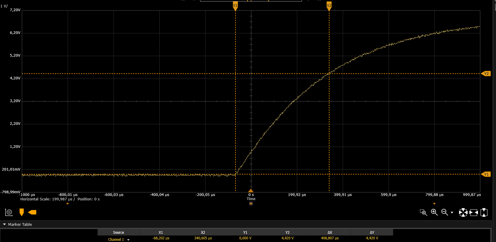
Calculated with: Load time divided by R1 I tried with the load formula solved to get C. I get a slightly different result but still nearly 4nF. When I measure without C2 and then with and substract the result, I get the CAP (Result varies a bit, but I guess thats a user error)

What am I missing here?

Edit

I can remove C2 freely, so even if the CAPs have toleranz I have the possibility to remove C2 - make a measurement - and then add C2 and compare the two measurements.

\$\endgroup\$

2 Answers 2

2
\$\begingroup\$

C1 and R2 are a highpass filter which should send noise in the upper 100MHz against ground. - Can I ignore this part for the calculation?

No, you cannot ignore this.
Compared to the other resistors, R2 is almost a short circuit. So, C1 is parallel to C2 (next to C5 already mentioned by X J).

I assume that R1 is my load resistor and I can ignore the R2-R5 for loading.

No, you neither can ignore those resistors. Compared to R1 you can ignore R2: you can approximate it as a short circuit as described above.
You can definitely not ignore R3+R4 and R5 because they have (about) the same value as R1.

Conclusion:
τ is defined by C2 and C5 as well as C1 and by R1 as well as R3+R4 and R5.

As X J already pointed out: C2 is hardly detectable as it is even smaller than the tolerances of C5, and as shown above, of C1.

Next to the tolerances, capacitor value can change with temperature and applied voltage as well. Measuring with an RCL meter will not cancel these last parameters out.

\$\endgroup\$
2
  • \$\begingroup\$ So is my tau approximately (C1 + C2 + C5) * (R1+(R3+R4)//R5) ? In the case I ignore R2? If I do that I get a tau of around 2ms (in the simulation I get that it should be 0.5ms, ignoring R2) so I guess that the formula is not right and R2 is massively influencing the load sequence. \$\endgroup\$
    – Eggi
    Commented Feb 4, 2020 at 8:22
  • \$\begingroup\$ R2 is not influencing the loading too much, overlooked something. \$\endgroup\$
    – Eggi
    Commented Feb 4, 2020 at 8:29
1
\$\begingroup\$

It's going to be hard because C2 (85pF) is in parallel with C5 (10nF), but less than 1% of C5. The capacitance's tolerance would normally be higher than 5%.

\$\endgroup\$
1
  • \$\begingroup\$ Ok, I can freely remove and add C2, so I can compare my measurements. \$\endgroup\$
    – Eggi
    Commented Feb 4, 2020 at 8:15

Your Answer

By clicking “Post Your Answer”, you agree to our terms of service and acknowledge you have read our privacy policy.

Not the answer you're looking for? Browse other questions tagged or ask your own question.