1
\$\begingroup\$

I am not an electrical engineer. I’m experimenting with an ESP32 Dev Kit.

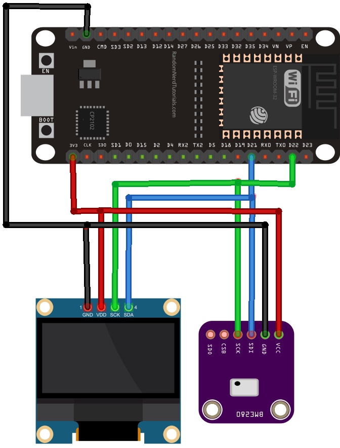
I was looking at this image:

multiple devices on single i2c bus

I had a couple if questions.

  1. In this diagram, there are two devices connected to the 3v3 pin. Is there any limit to the number of devices that can be connected to that pin, so as not to damage anything?

  2. Multiple i2c devices are connected to the same pins (21,22). How can I determine how many more devices I can connect to the same bus without damaging anything?

I guess what I’m trying to figure out is, when looking at the data sheet for my devices, what should I look for, so I can compute how many I can connect to a single esp32 in this fashion (same i2c bus, same 3v3 and gnd pins).

\$\endgroup\$

3 Answers 3

1
\$\begingroup\$

In this diagram, there are two devices connected to the 3v3 pin. Is there any limit to the number of devices that can be connected to that pin, so as not to damage anything?

You'll have first to understand what is the power regulator on that development board and how much current at the 3.3V voltage can it deliver (output current capacity). Then, you'll need to figure out both the device's maximum current consumption (how much current they are each sinking).

Once you got the 2 current numbers for the devices, add them up and verify that the sum doesn't exceed the power regulator current capacity. This quick method should guarantee that the 3.3V rail stays at that voltage value and does not drop under.

To really damage the power regulator, you may have to try harder as most power regulators monitor their output current and if their limit is exceeded they will protect against permanent damage. Low-dropout voltage regulators tends to be more "fragile" than DC-DC converters. Do you have a part number for this regulator?

Multiple i2c devices are connected to the same pins (21,22). How can I determine how many more devices I can connect to the same bus without damaging anything?

As long as you connect the I2C lines correctly to each device, you wouldn't damage anything.

I2C bus relies on external pull-up resistors for the rising edges of the signal. These resistors do exactly what they are intended to which is to pull the voltage on the bus back to the "high" state (or in your case, it would be 3.3V). Because of their current-limiting property, the resistor can only pull the bus back up at a limited rate (the bus needs to source current from 3.3V rail to "recharge" itself).

The more devices you have on the bus, the more it needs current from 3.3V to recharge itself and the slower the rising edge of the signal will be. At one point, with many, many devices connected, the edge will be so slow that you will "break" the data integrity of the bus (eg. you won't be able to read correct values from devices anymore). However, the hardware itself will remain fine.

\$\endgroup\$
5
  • \$\begingroup\$ That explains a lot! Does that mean (to test it), I can just keep adding devices until I get bad values? No risk of anything getting damaged? All the devices I am adding are breakout boards like bno055 or drv2605L . \$\endgroup\$ Commented Feb 4, 2020 at 12:39
  • \$\begingroup\$ @KaizerSozay I think you could try that if you know how to detect and filter "bad" values from "good" ones, no risk of getting damaged. If you can't figure out if the values are "good" or not, you'll need a bit more equipment to verify the I2C bus data integrity (like a protocol analyzer and/or oscilloscope). \$\endgroup\$
    – eeintech
    Commented Feb 4, 2020 at 13:41
  • \$\begingroup\$ For sensors I can test the data. But linear resonance actuators (motors) connected to drv2605L (motor driver), do not provide any data back... I just send instructions on how to vibrate. So in such devices, I guess they won’t vibrate properly? \$\endgroup\$ Commented Feb 4, 2020 at 13:50
  • \$\begingroup\$ @KaizerSozay Even if the motor driver does not send data back, to be I2C compliant it needs to send an acknowledgement when it receives its address and following data, you could check that the ACK has been recorded by the master to confirm the motor driver got the instructions. Then to know if you send the correct instructions (like frequency, drive strength, etc.) you'll then have to "feel" it :) \$\endgroup\$
    – eeintech
    Commented Feb 4, 2020 at 14:46
  • \$\begingroup\$ Ok, that makes sense! 👍😆 \$\endgroup\$ Commented Feb 4, 2020 at 15:06
1
\$\begingroup\$

As I can see from the data sheet of the ESP32 it specifies Ioutput* Cumulative IO output current - 1200 mA * The chip worked properly after a 24-hour test in ambient temperature at 25 °C, and the IOs in three domains (VDD3P3_RTC, VDD3P3_CPU, VDD_SDIO) output high logic level to ground.

So as long as your slaves total current consumption doesn't exceed the 1200 mA you should be good, also keep in mind that the wireless transmission will use a lot of that supply.

-- Side note from the data sheet regarding the power supply "its recommended output current is 500 mA or more" .. This is to support said wireless transmission --

As for multiple I2C devices, the bus supports a capacitance of 400 pF, and a max of 127 addresses. That doens't mean you can support the 127, as it all comes down to the capacitance of the bus.

\$\endgroup\$
4
  • \$\begingroup\$ In i2c, a device is connected to SDA, SLC, 3v3 and GND. Does that mean the device draws all its power via 3v3? If that is the case, by connecting the 3v3 & gnd of the device to a separate power source, rather than that of ESP32, will I be outside this limit? \$\endgroup\$ Commented Feb 4, 2020 at 12:00
  • \$\begingroup\$ Also, can you explain about the capacitance of the bus? How do I calculate how many devices I can support? \$\endgroup\$ Commented Feb 4, 2020 at 12:01
  • \$\begingroup\$ Yes external PSU will mitigate the load on the ESP32, as for the I2C bus calculations give this a read microchip.com/forums/m1011861.aspx \$\endgroup\$
    – Sorenp
    Commented Feb 4, 2020 at 12:06
  • \$\begingroup\$ I don’t think sleep routines matter. Just didn’t want to fry my esp32 during a live presentation. \$\endgroup\$ Commented Feb 4, 2020 at 12:07
1
\$\begingroup\$

How do I calculate how many I2C devices can be connected

Bus capacitance is the sum of all capacitances. Every pin has a capacitance associated with it. Most of them will be around 10pF. You can find this information in the datasheet of the devices.

So, assume you are connecting 5 such devices. Then total capacitance will be 50 pF. The PCB traces, the wires all will have some parasitic capacitance too. Asse it to be around 20 pF. So total is 70 pF. This is within the bus capacitance limit of 400 pF.

Multiple solutions exists to even mitigate this limitation

\$\endgroup\$

Your Answer

By clicking “Post Your Answer”, you agree to our terms of service and acknowledge you have read our privacy policy.

Not the answer you're looking for? Browse other questions tagged or ask your own question.