As you correctly pointed out, a quasi-square-wave resonant converter colloquially called a quasi-resonant converter (QR) is a self-relaxing converter: there is no clock in the controller except for clamping purposes. The switching frequency varies with operating conditions. It is low at low line and high power, it is high at high line and low power.
QR converters are popular for various reasons:
- they always operate in discontinuous conduction mode (DCM) regardless of the operating conditions.
- as such, they remain a 1st-order system and are easy to stabilize in current-mode control.
- if you insert a deadtime before turning on the power switch, you can wait that \$v_{DS}(t)\$ goes through a minimum or a valley - hence the term valley-switching operation - and reduce switching losses potentially to zero (ZVS) if the valley touches ground.
- because of the DCM operation, driving a synchronous rectifier is safer than in continuous conduction mode (CCM) as shoot-through currents are minimized.
- excellent behavior in short circuit and the output diode loves it. It was one reasons QR converters were popular in CRT TVs applications with a lazy high-voltage diode and a high-voltage output rail.
They have some drawbacks however:
- frequency varies along the operating range.
- over-power is a problem in ac-dc application: the available power at low line is more than doubled at high line and overload management is tricky.
- high ripple current forcing the selection of costly output capacitors subject to a high rms current.
- can be noisy in short circuit situations and some customers may not like it (I had the case once).
Here is shot of a typical drain-source voltage where the valley is clearly seen:

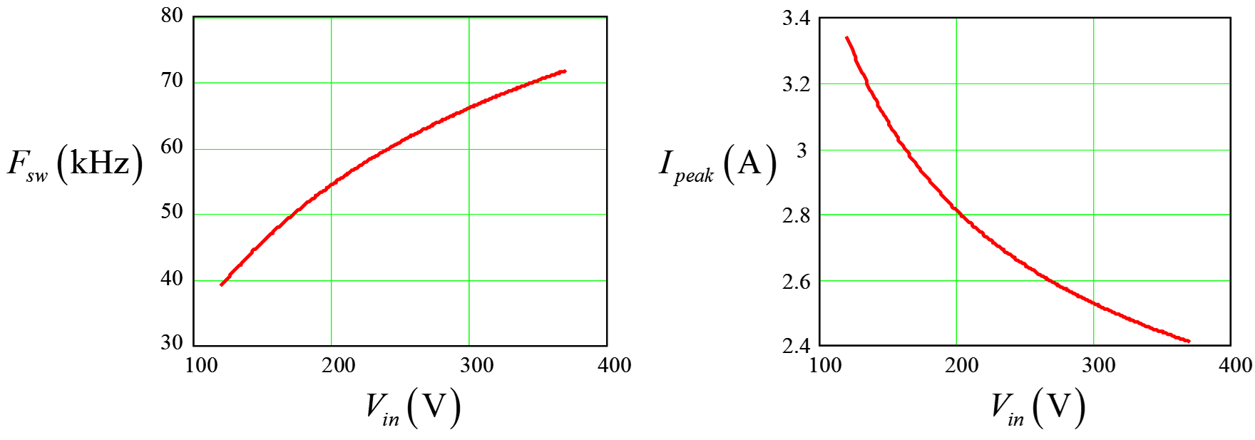
In peak current mode control, the loop adjusts the setpoint and indirectly fixes the on-time considering the primary inductance and the input voltage. The off-time slope is constant and depends on the reflected output voltage. Then you add the deadtime DT to ensure valley switching. Below is shot of the operating frequency and peak current as described in the book I wrote on power supplies:

Now that we know a little more about this converter, let's see your questions:
- How do I select the operating frequency? There is no straight answer as you can imagine but in ac-dc application, people want to stay away from the audible range. They select the primary inductance and transformer turns ratio so that at full power and low line, the converter operates beyond the 30-kHz range. That being said, the power delivered by a discontinuous conduction mode (DCM) flyback depends on the frequency and peak current. Therefore, staying above 30 kHz is one thing but you may want to operate closer to 50-60 kHz to reduce the peak current and limit the transformer size. Then, you know that switching frequency is going to increase as the line goes up but also when the load gets lighter. What maximum frequency you want to limit yourself to? Because we know the losses high-frequency operation will bring but also electro-magnetic interferences (EMI). So you have to go through iterations with these goals in mind and see what transformer size each scenario (what min and max frequencies) brings.
- Regarding the transformer: no, the primary inductance \$L_p\$ does not change along the operation unless you approach saturation of course. We know transformer losses - copper and iron - will increase as \$F_{sw}\$ and efficiency will suffer. It is clear that if your nominal operating point is 400 kHz, you'll have to select wires and core accordingly. If your nominal point is 70 kHz and you go to 150 kHz in light-load condition before the frequency is clamped, then obviously we are talking about different conditions for the transformer. So once you have run a few iterations on the inductance selection, the transformer turns ratio and so on, you will have a better picture of what the nominal operating frequency is and which wire and core material to favor.
As a final note, carefully look at the controller offer as many different strategies exist. I personally like a free-running operation until a maximum frequency is reached (frequency clamp) so that you limit losses and then gradually reduced by a voltage-controlled oscillator (VCO) as the load current is getting lighter. Plenty of chips to choose from!


