0
\$\begingroup\$

I am still trying to build a simple audio amplifier using the LM386. I also found some older LM386 in my department, since my previous batch may be corrupted.

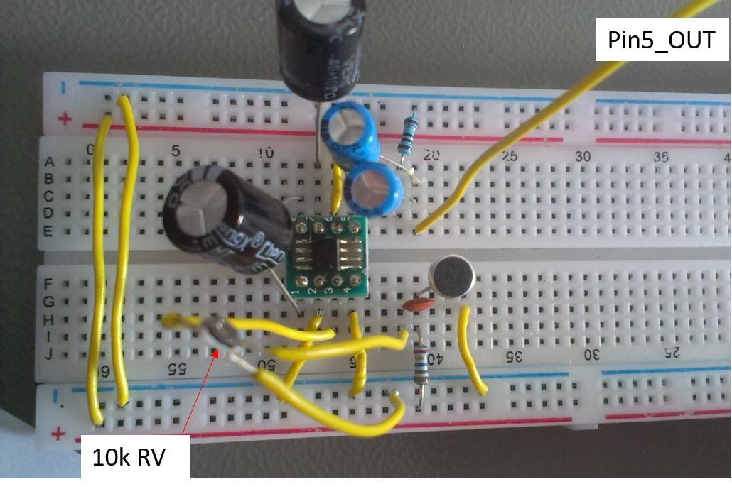
Using this circuit I rebuilt it using a breadboard.

lm386_simple

On the Pin5_OUT are headphones and an oscilloscope. The circuit is powered with the 5V output of an Arduino Nano.

Measuring key points:

  • V_pin5out = 0.825V (better than the 0V from my previous circuits, but still not 2.5V)
  • V_DD = 4.71V (between the 5V pin of the arduino and GND)
  • V_pin6 = 4.65V (supply pin of the chip).

There is still no audible output from the headphones and in addition the chip gets extremely hot (I pulled the plug at around 80°C).

Is there an error in my the circuit (picture above)?

Are these normal operating conditions?

Are the 2.5V bias measured only at low noises and change with the volume?

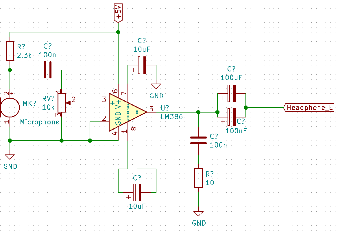
EDIT: I draw a schematic as I see the board, since the picture seems to be confusing lm386_real
\$\endgroup\$
20
  • 1
    \$\begingroup\$ Is there an error in the circuit? - what circuit? \$\endgroup\$
    – Andy aka
    Commented Feb 17, 2020 at 11:34
  • 2
    \$\begingroup\$ A pic of a messy breadboard isn't a schematic. We'd need the schematic you based the breadboard circuit on. Though overall, error and breadboard are pretty much synonymous. Soldering is always preferable. \$\endgroup\$
    – Lundin
    Commented Feb 17, 2020 at 11:43
  • 1
    \$\begingroup\$ the chip gets extremely hot Smells like you suffer from oscillations. Did you follow the PCB layout example as shown in the datasheet? Did you add all the components as suggested in the schematic in the datasheet? The LM386 has a sensitive input but (relatively) high current output so you have to make sure that the output current doesn't feed back into the input. If it does, you might get oscillations and those can heat up the chip. Maybe a minor issue but not all pins on the adapter board appear to be soldered properly. \$\endgroup\$ Commented Feb 17, 2020 at 11:59
  • 1
    \$\begingroup\$ Oh and these oscillations may be due to having no bulk or bypass capacitors on LM386 supply pins. \$\endgroup\$
    – Justme
    Commented Feb 17, 2020 at 12:04
  • 1
    \$\begingroup\$ I am at a loss to explain your problems. The LM386 is normally a stupidly simple chip to use. I built amplifiers with them when I was a kid. No Zobel network, no bypass capacitor on pin 7, no bypass on pin 6, and it just worked. Are you sure that's an LM386 at all? The markings on the chip itself are just a fuzzy blob in all your pictures. Can you double check? \$\endgroup\$
    – JRE
    Commented Feb 17, 2020 at 12:25

0

Your Answer

By clicking “Post Your Answer”, you agree to our terms of service and acknowledge you have read our privacy policy.

Browse other questions tagged or ask your own question.