0
\$\begingroup\$

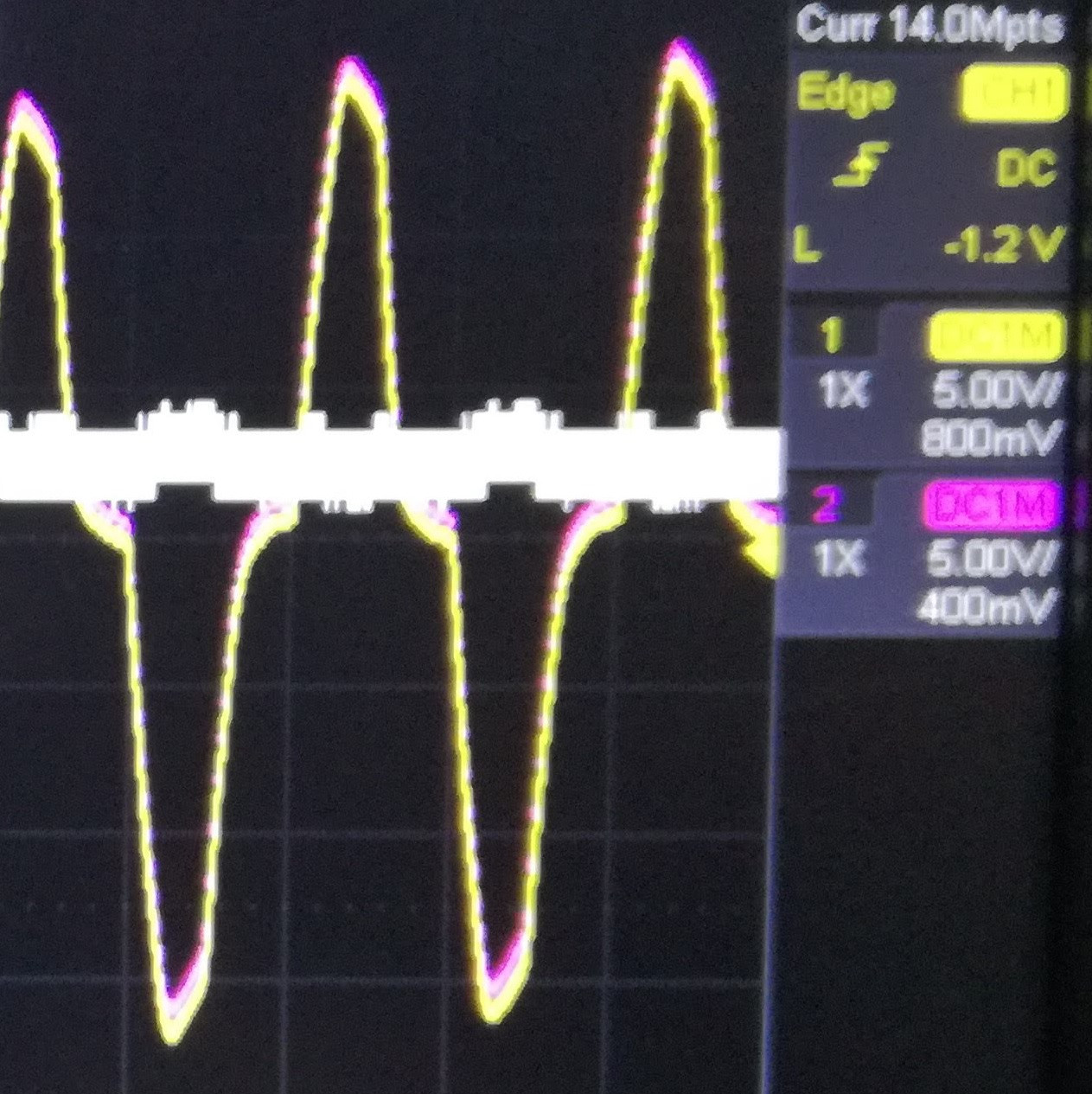
Good morning, I have a power supply with floating ground that drives my circuit. Since the circuit doesn't work as expected (it works fine only if the ground is tied to earth) I did some measures with oscilloscope. I left the ground of both probes (with 10x) disconnected and I did the difference between the two channels connected respectly to gnd and to the input signal of an opamp. What I see (see picture) is that the difference (white band) is not flat but there are peaks oscilloscope picture I'm wondering if: - it's a my mistake in the measure or - the two points don't float together creating a voltage difference in the opamp input - there is a way to reduce the float voltage difference

Thanks

\$\endgroup\$
2
  • \$\begingroup\$ What power supply? Link or datasheet please. Does it have 2-prong (unearthed) or 3-prong (earthed) plug? \$\endgroup\$
    – Justme
    Commented Feb 25, 2020 at 21:58
  • \$\begingroup\$ I tried with different power supply, all unearthed. \$\endgroup\$
    – Fabio
    Commented Feb 26, 2020 at 21:39

3 Answers 3

3
\$\begingroup\$

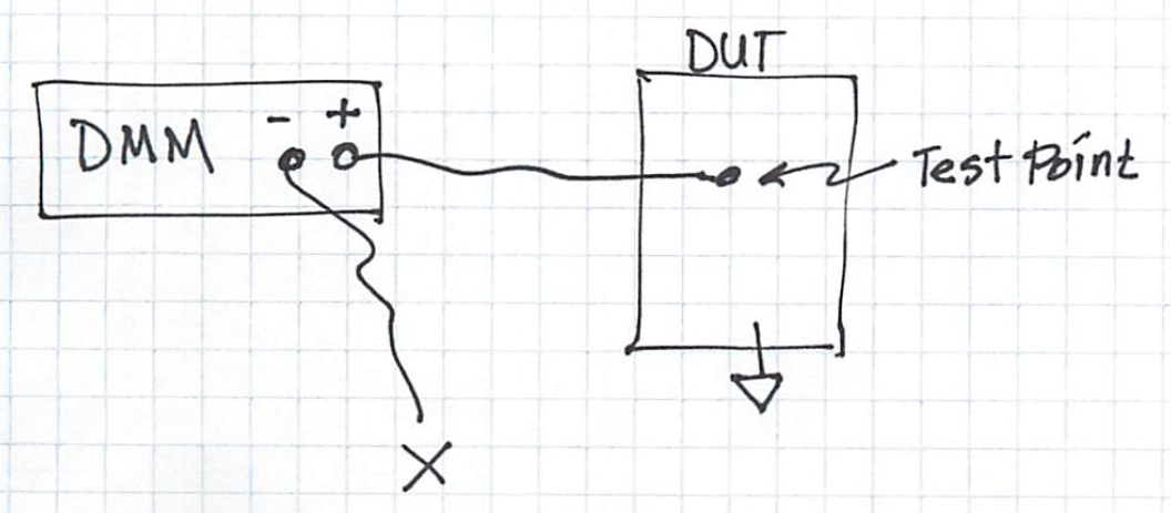
Your measurement technique is invalid. See Fig. 1. Imagine that instead of using an oscilloscope you have a multimeter, and you connect only the meter's "+" probe to the test point on the device under test (DUT); you leave the meter's "-" probe disconnected from the DUT. The multimeter performs a voltage measurement and displays a voltage value. Is the displayed voltage value a valid representation of the voltage between the DUT's test point and the DUT's ground reference potential?
enter image description here

Figure 1.

The answer is "It depends." If the multimeter's "-" input randomly happens to be at the same potential as the DUT's ground reference potential, then the voltage value shown on the multimeter is probably valid; otherwise it is definitely invalid.

Now imagine using two DMMs. The negative terminals of the two DMMs are connected together, but as before the negative terminals are not connected to the DUT. The positive terminals on the two DMMs are attached to two different test points on the DUT. Both DMMs make a voltage measurement. In this scenario, does each individual multimeter make a valid single-ended voltage measurement? If the answer is "No" (and it is "No"), one cannot now synthesize a valid differential voltage measurement by calculating the difference of the two invalid single-ended voltage measurements.

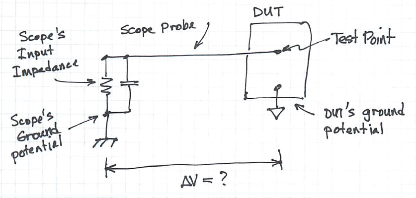
Also consider Fig. 2. Ask yourself this question: "What is the voltage across the resistor on the left side of the figure?" (which represents the input impedance at the oscilloscope's analog input). It's impossible to say what the voltage is because you cannot know voltage ΔV, the change in voltage between the oscilloscope's chassis ground (which is usually Earth ground) and the DUT's "floating" ground potential. (HINT: Using Kirchoff's Voltage Law, start at the oscilloscope's chassis ground potential and add up the voltage drops from that chassis ground node to the top of the resistor at the oscilloscope's input; that sum—i.e., the voltage across the resistor— is the voltage the oscilloscope measures.) Because voltage ΔV is undefined, the oscilloscope measures a random voltage.
enter image description here

Figure 2.

Now imagine repeating Fig. 2 with two analog input channels on the oscilloscope, leaving the probe grounds disconnected and connecting the probes to different test points on the DUT. Both analog inputs perform a single-ended voltage measurement that yields a random voltage value for each channel. These two random voltages cannot be synthesized into a valid differential voltage measurement by subtracting one from the other.

To make this measurement you should use

  • A battery-powered oscilloscope that is not connected to Earth ground potential, OR

  • A differential voltage oscilloscope probe (Keysight Labs video on YouTube), OR

  • An oscilloscope whose input channel(s) can be safely isolated from chassis (Earth) ground potential, OR

  • A custom measurement setup that uses (for example) an isolation amplifier that provides galvanic isolation between the oscilloscope ground potential and the DUT's floating ground potential.

See also:
\$\endgroup\$
2
  • \$\begingroup\$ You say "Both analog inputs perform a single-ended voltage measurement that yields a random voltage value for each channel. These two random voltages cannot be synthesized into a valid differential voltage measurement by subtracting one from the other." If I'm not wrong the random voltage, since it's the same for both channels, is cancelled during the subtraction. \$\endgroup\$
    – Fabio
    Commented Feb 26, 2020 at 21:50
  • \$\begingroup\$ I isolated the oscilloscope from earth but, when I connect the gnd of the probe to my circuit, it starts to work. It seams that every action that just reduce the floating voltage on my board solve the problem, so it's not easy to check the board leaving the problem active. \$\endgroup\$
    – Fabio
    Commented Feb 26, 2020 at 22:00
1
\$\begingroup\$

Most isolated power supplies will have a certain amount of leakage from primary to secondary. This is because there is some capacitive coupling across the transformer. You can see this leakage if you measure the AC voltage of your floating secondary, which might be surprisingly high but at very low current.

Now, where the problems begin to occur is if the secondary encounters something that is grounded - or has a path to ground (like your hand, for example.) The leakage noise is looking for a path to ground, and if it finds one, you get noise.

So you’ve already found a solution: grounding the secondary side to shunt this leakage away from your sensitive circuitry. Another solution is to shield the sensitive stuff so it can’t couple to a nearby source.

\$\endgroup\$
3
  • \$\begingroup\$ The description on the first part is exactly what I see but if I touch the gnd of my circuit it starts to work. \$\endgroup\$
    – Fabio
    Commented Feb 26, 2020 at 22:04
  • \$\begingroup\$ That means your hand is providing a path to ground. If you make an explict tie to ground that should work as well. \$\endgroup\$ Commented Feb 26, 2020 at 23:04
  • \$\begingroup\$ yes, it's clear form me, but before you said that " where the problems begin to occur is if the secondary encounters something that is grounded" in my case the problem doesn't begin but ends. \$\endgroup\$
    – Fabio
    Commented Feb 27, 2020 at 18:00
0
\$\begingroup\$

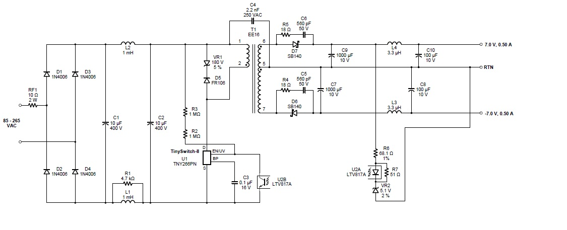
enter image description here

check C4 capacitor in ur power supply as in my picture.

\$\endgroup\$
2
  • 2
    \$\begingroup\$ Where did this schematic come from and does it relate to the question? \$\endgroup\$
    – David
    Commented Feb 25, 2020 at 22:49
  • \$\begingroup\$ Do you say that using a capacitive coupling across primary and secondary, as in your picture, help to solve my problem ? In which way? In any case the power supply is external to my board. \$\endgroup\$
    – Fabio
    Commented Feb 26, 2020 at 22:15

Your Answer

By clicking “Post Your Answer”, you agree to our terms of service and acknowledge you have read our privacy policy.

Not the answer you're looking for? Browse other questions tagged or ask your own question.