1
\$\begingroup\$

I have a very simple setup powered by a 9 V battery. The lock solenoid when connected directly to the battery works great.

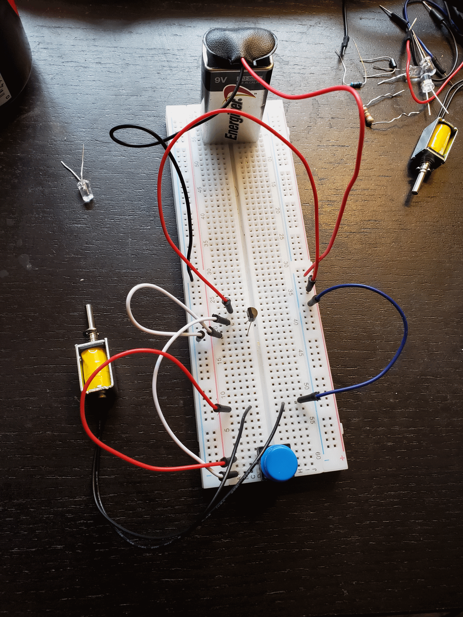
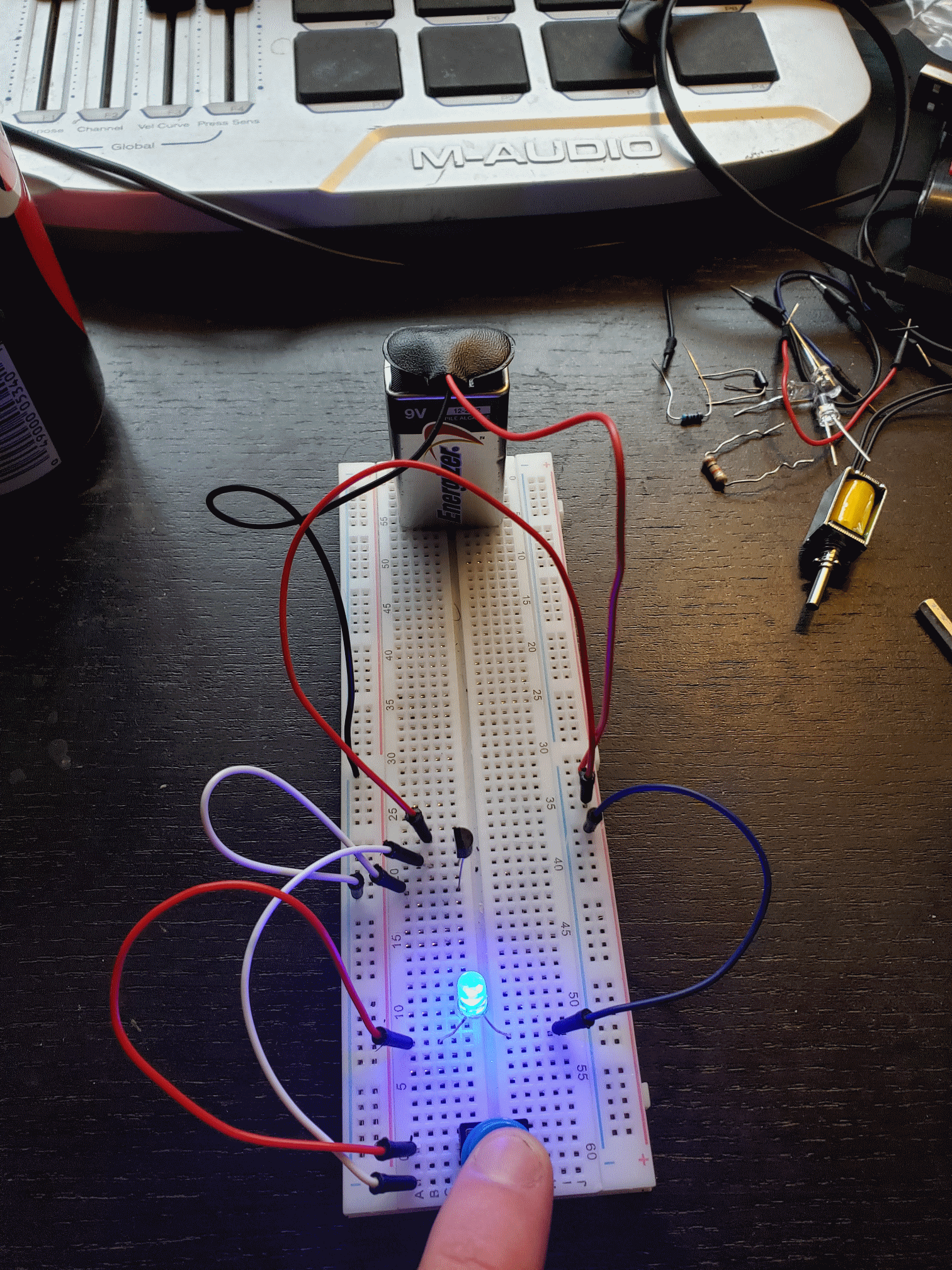
I have built a test circuit using a push button and a transistor in an attempt to make it so that when I press the button down the lock solenoid will power up. This circuit works fine with an LED, but does nothing at all when I swap the LED for the lock solenoid. I have tested this with a DC motor and lock solenoid. Both the motor and solenoid are 4.5 V and work when directly connected to the battery, but not when replacing the LED in the circuit. I will attach some photos of the circuit.

I have been messing with this for days with no progress. My ultimate goal is to control this solenoid with an Arduino Nano, but I could not get that working so I am trying to get it working with the push button acting as the Nano IO signal before I move further with the microcontroller.

Any advice at all would be appreciated, I am still very new to all this.

Circuit photos attached below:

Solenoid Circuit

Led Circuit

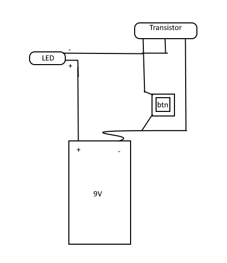
Crude Schematic

\$\endgroup\$
12
  • \$\begingroup\$ Post your schematic. \$\endgroup\$
    – user16324
    Commented Mar 3, 2020 at 18:28
  • 1
    \$\begingroup\$ Note the statement "it works" does not mean "it is correct". So, the LED burns does not mean the circuit is as it should be. The circuit is missing (current limiting) resistors and the switched current seems to be running through the button (whic shouldn't as that is the reason to use a transistor+button instead of only a button). Please add the schematic you used or provide the transistor type and pinout \$\endgroup\$
    – Huisman
    Commented Mar 3, 2020 at 18:53
  • \$\begingroup\$ Looks like the switch is in series with the LED or solenoid, rather than controlling the transistor. Please show a schematic of your circuit, and include the transistor part number. \$\endgroup\$ Commented Mar 3, 2020 at 18:54
  • \$\begingroup\$ The photos of the circuits are all I have. I have not drawn a schematic. I am certainly a noob to all of this, but I tried it with multiple different resistor with the same outcomes. I just do not understand how the led could work, but not the solenoid once the led is in place. Even though the power supply will directly power either one of them. \$\endgroup\$ Commented Mar 3, 2020 at 18:58
  • 1
    \$\begingroup\$ Why don't you use the built in schematic editor? How can we know which pin of your transistor serves which function? Btw it is a little miracle that your circuit produces blue light without magic blue smoke. \$\endgroup\$
    – Ariser
    Commented Mar 3, 2020 at 19:58

1 Answer 1

1
\$\begingroup\$

I don't see any resistors in your circuit, only a transistor in the TO-92. So probably your transistor is MOSFET and its Ron is too high. Try another transistor with lower Ron (1..50mΩ). LED requires just few mA to illuminate unlike the solenoid which requires much higher current to turn on.

\$\endgroup\$
3
  • \$\begingroup\$ I have added a very crudel drawn schematic. This is my first schematic ever, but hopefully it helps. \$\endgroup\$ Commented Mar 3, 2020 at 19:33
  • \$\begingroup\$ Very similar question is here: electronics.stackexchange.com/questions/210437/… \$\endgroup\$
    – Peter MP
    Commented Mar 3, 2020 at 21:07
  • \$\begingroup\$ Yeah... it's unclear what kind of transistor it is, or how much current he's expecting to draw through the solenoid. \$\endgroup\$
    – MadMan2064
    Commented Jan 29, 2021 at 3:38

Your Answer

By clicking “Post Your Answer”, you agree to our terms of service and acknowledge you have read our privacy policy.

Not the answer you're looking for? Browse other questions tagged or ask your own question.