3
\$\begingroup\$

I am making a bot capable of solving a maze.

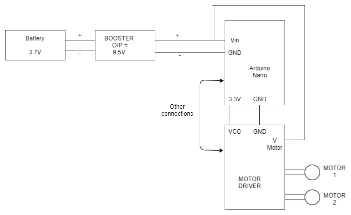
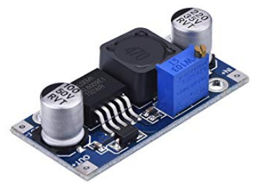
I will explain the setup first. There is a 18650 3.7V battery, using a XL6009 DC-DC boost switching regulator, like this one:

enter image description here

Picture Source

I boost the voltages up to 9.5V. Then I make 2 parallel lines. One goes to the Motor Driver voltage (motors work fine at 10-12V). The other end goes to the Vin of the Arduino.

When I attempt to test the motors, the Arduino sort of resets everytime although it works fine if I test some other peripherals and disconnect the motor driver and hence the motors.

Again the motors work fine, if I power the Arduino separately like from a 9V battery keeping the rest of the circuot as it is.

What am I doing wrong?

Will connecting a linear regulator like 7809 / 7805 in series before powering up the Arduino help ?

enter image description here

\$\endgroup\$
4
  • \$\begingroup\$ What motors are you using? \$\endgroup\$ Commented Mar 7, 2020 at 9:07
  • \$\begingroup\$ polulu micrometal gear motors 12V N20 . pololu.com/category/60/micro-metal-gearmotors \$\endgroup\$
    – Healer77Om
    Commented Mar 7, 2020 at 11:09
  • \$\begingroup\$ Your wiring diagram appears to show ground going to the Arduino first, then through it to the motor controller. Is that how you have it wired? \$\endgroup\$ Commented Mar 7, 2020 at 12:04
  • \$\begingroup\$ yes . should i connect it separately ? \$\endgroup\$
    – Healer77Om
    Commented Mar 7, 2020 at 16:08

9 Answers 9

7
\$\begingroup\$

I agree with @vtolentino's assessment that the DC motor's startup current is so large that the motor overwhelms the XL6009 DC/DC converter. The converter's output voltage has a momentary but significant voltage droop (a.k.a., a voltage brownout) that causes the microcontroller to reset itself. This can be confirmed by monitoring the DC/DC converter's output voltage with an oscilloscope and observing what happens to the voltage amplitude when the DC motor starts up. (NB: And I would not be surprised if the 9.5 VDC power rail has significant noise on it when the DC motor is running. This noise can easily cause the microcontroller to reset itself, and can cause erratic data when performing analog-to-digital conversions, etc.)

As a general rule, one should not power both a digital load (like a microcontroller) and a motor load from the same power rail. A far better approach is to create/use separate, independent power sources for the digital load and the DC motor. For example, connect two XL6009 DC/DC converters to your battery. Use one XL6009 to supply power the microcontroller, and use the second XL6009 to supply power the DC motor. Connect together the grounds at the outputs of the two XL6009 boards so that they share a common ground potential.

\$\endgroup\$
4
  • \$\begingroup\$ if i add a LM 7809 linear voltage regulator in series with the booster before powering my uC and power the motors from the booster itself , can it solve the problem ? Stall current of my motors is 0.75A . \$\endgroup\$
    – Healer77Om
    Commented Mar 7, 2020 at 11:17
  • \$\begingroup\$ If the XL6009 experiences voltage droop at its output at motor startup, the LM7809 momentarily loses input power resulting in a voltage droop at the LM7809's output. So doing nothing more than adding an LM7809 will not solve the problem. Others have suggested adding one or more large-valued electrolytic capacitors as energy storage reservoirs. At motor startup, the motor draws energy from both the XL6009 and the capacitors, which hopefully mitigates the overload condition on the XL6009, and thereby prevents excessive voltage droop on the +9.5 VDC power rail at motor startup. \$\endgroup\$ Commented Mar 7, 2020 at 18:33
  • \$\begingroup\$ (cont.) Adding a large-valued electrolytic capacitor at the DSL6009's output must be done with care. At power up, a large-valued capacitor connected to the DSL6009's output appears as a momentary short circuit load; therefore, at power up the DSL6009 must supply a VERY LARGE--albeit momentary--surge of output current to "charge up" the large capacitive load at its output. The components on the DSL6009 board that source power to the board's output must all be designed to safely tolerate this momentary current surge when the DSL6009 powers up. \$\endgroup\$ Commented Mar 7, 2020 at 19:11
  • \$\begingroup\$ thanks a lot for teaching me how to handle this condition . \$\endgroup\$
    – Healer77Om
    Commented Mar 7, 2020 at 21:53
7
\$\begingroup\$

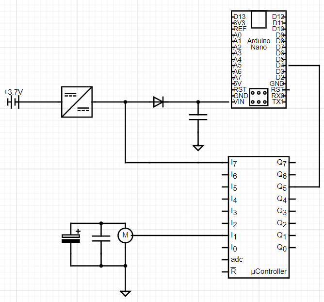
From your setup, I assume that the motor (not only the driver) is also being supplied by your booster. At start up the motors draw a lot of current, thus dropping the supply line voltage down to a point where the RESET pin of the arduino is active. You could do one of or a combination of the following:

  • Add a capacitor at the input of the motor (or increase the already existent), in order to cope with this in-rush current.
  • Add a diode / rectifier at the input of the arduino and a capacitor after that in order to prevent the motor from drawing current from the arduino's input capacitance.
  • Add a current limiter to the motor line, e.g.: a) NTC thermistor (Keep in mind that it becomes useless if the motor is turned on/off/on very within a short period of time) or b) an FET / BJT based current limiter. Both solutions will add to the power loss in the system.

Circuit

\$\endgroup\$
5
\$\begingroup\$

"My arduino controlling motors crashes when motors actuate".

This is a frequently asked question here. What's happening is you wired it so the Arduino takes power from the same point in the wiring as the motor, and the wiring or the supply is sagging voltage because of the motor's load. This is normal. Motors do that. They should not be on the same wiring/supply. I can't tell you how many of these we fix simply by pulling a dedicated pair of wires from the power source just for the Arduino, or in your case, a dedicated DC/DC.

The gory details

Your $1.57 DC/DC has a capacity of 4A on the input side (3.7V), so we are talking 14.8 watts of supply power, gross. Let's toss it a bone and assume 85% conversion efficiency, now we have 12.58 watts.

Your motors have a Locked Rotor Amerage of 750ma at 12V, or 9 watts. You have two of them. Uh-oh.

Now, if we bet the farm on these motors being resistive, then E=IR
12V=0.750A x R
R=16 ohms
9.5V=I * 16 ohms if it's a resistor I = .59375A hopeful locked rotor amperage P = .59375A x 9.5V = 5.64 watts
2 motors = 11.28 watts = you are really pushing a 12.58W source

So you see, even in the most optimistic case: 85% efficiency, purely resistive motors, disregarding the Arduino's draw and the motor controller's efficiency -- you are kissing the absolute limits of the power supply.

Since this is a $1.57 DC/DC from China, I would not expect good performance at the edges of the envelope.

The $1.57 solution is to get another one to power the Arduino, and let the motors sag. Motors do that, nobody cares.

That's if your Arduino even needs 9.5V. If it can run on 3.3V, then hotwire it straight off the battery. By which I mean straight off the battery, not off the input side of the DC/DC: they are not the same thing because wires are not 0 resistance.

\$\endgroup\$
2
\$\begingroup\$

The inrush current of the motor will be the suspect. You can confirm it by watching the output voltage of the boost using an oscilloscope when you drive the motor.

  1. Add capacitors, suitable big value. Also a series Resistance so that it takes a while to charge..else it will act like a short for the boost when you power on for the first time.

  2. You can also plan for a dedicated Load switch. The load switch will control the current based on the preset rise time.

  3. You can also slowly increase the speed of the Motor instead of doing form off to full on directly.

  4. I assume you already have flyback diodes as ell across the motor

\$\endgroup\$
0
\$\begingroup\$

There are several reasons that causes a microcontroller to reset. In your case, these are the most probable factors:

1- Reset pin --> check if its is driven low or floating. 2- ESD on Reset pin --> Check that enough decoupling and bypass capacitors are attached (Normally 1uf and 100nF very close to the reset pin). 3- Power rail falling below nominal voltage when motor starts --> Add enough decoupling cap (say 1000uF) across power rails.

Also you can do some extra care: 1- Separate analog and digital ground with some ferrite bead. 2- Add good quality bypass tantalum cap (100nF) across the motor. 3- Make sure that your motor driver has some sort of flyback diode.

\$\endgroup\$
0
\$\begingroup\$

XL6009 min input voltage is 5V (see datasheet). Not only it will not supply necessary current, but when voltage of liion goes below 3v XL6009 fails to regulate properly and voltage spikes on output. Observed this behaviour on two units. Summary is that XL6009 is not suitable to boost liion bateries. What I recently used on few projects to boost liion voltage is cheap "power bank" circuits. By default those boots liiov voltage to 5v. I modified feedback voltage divider to increase this voltage to my needs. Don't forget to remove USB output if you do that! You do not want to burn USB device with overvoltage by mistake.

\$\endgroup\$
0
\$\begingroup\$

Please add large electrolytic capacitor at the output otthe DC to DC booster like 2200uF 25V and the supply voltage point between arduino and the motor board may be 1000uF 16V and connect the ground point from booster to motor board directly

\$\endgroup\$
0
\$\begingroup\$

Adjust the power supply in the buck boost converter once after connecting both the arduino and motor cause there will be significant power(voltage) drop. For eg. To power 1 high power 1w led the buck converter requires 3.3v output but when the same buck converter powers 15x1w led connected in parallel requires a slight increase in power output so there is a need of adjustment with multimeter connected in parallel to get the exact power which is in need.

\$\endgroup\$
0
\$\begingroup\$

Look, if you use a DC-DC module for the Arduino and a separate one for the motor drive, it will work, but that's where the move comes in: use a diode to divide the input between the two, with the diode the drive the motor will not use the current from the Arduino module. It's quite simple.

\$\endgroup\$
1
  • \$\begingroup\$ Please only use English, that's the official language of the site. \$\endgroup\$
    – clabacchio
    Commented May 22, 2020 at 12:29

Your Answer

By clicking “Post Your Answer”, you agree to our terms of service and acknowledge you have read our privacy policy.

Not the answer you're looking for? Browse other questions tagged or ask your own question.