4
\$\begingroup\$

I bought a adl-65074tl-1 laser diode, I am trying to drive it and to read the feedback of the monitor photodiode with an oscilloscope. I am using a laboratory DC power supply and a multimeter for setting the voltage value of the diode to the 2.2 V (Iop). After some trial and error, I built this schematic, I've add the resistor and the condenser for reducing volage spikes, but the source is quite stable.
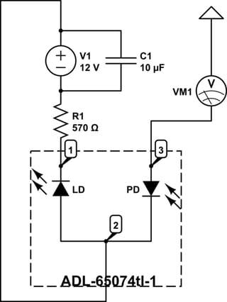
schematic

simulate this circuit – Schematic created using CircuitLab

I don't understand how to read the current or the voltage from the monitor photodiode that from the datasheet should be on the pin 3.

Edit

The voltmeter symbol should be replace with an amperemeter. Eventually, I've discovered that my multimeter had a blown fuse. Replacing it I was able to read the current.

\$\endgroup\$

2 Answers 2

5
\$\begingroup\$

The Photodiode needs to be in reverse mode, it is wired for that correctly already (+12 V at the kathode. The anode just needs to be at a voltage that is below 12 V.

When in reverse mode, a photodiode will output a current that is proportional to the amount of light. To measure a current you need to connect a current meter in series. So just replace the voltmeter with a current meter.

The way you connected the voltmeter makes little sense as a voltage should be measured in parallel with a device, not in series like shown. (You could argue that you're measuring Vsupply - Vdiode but as the diode is in reverse mode, that does not make sense).

\$\endgroup\$
2
  • \$\begingroup\$ Thanks, sorry I put the wrong symbol in the picture, it was meant to be an amperemeter. so I connected both to the same negative terminal but I don't see any variation on the current when I use for instance a reflector to reflect the laser inside the cavity \$\endgroup\$
    – G M
    Commented Mar 10, 2020 at 11:50
  • \$\begingroup\$ You should see a change in current when you change the current through the laser diode. And that's what the photodiode is supposed to be used for, an indication of the output of the laser diode. The light bouncing inside the cavity might never reach the photodiode. \$\endgroup\$ Commented Mar 10, 2020 at 12:01
3
\$\begingroup\$

What you have works !
The diode is reverse biased thru impedance of voltmeter to measure current in high impedance.

For improved BW or speed, use a TIA with lower R.

fWIW your schematic in upside down. Use ground at the bottom with V1- = 0V = GND

\$\endgroup\$
1
  • \$\begingroup\$ Thanks, eventually, I discovered that the multimeter had a blown fuse. It worked. \$\endgroup\$
    – G M
    Commented Mar 11, 2020 at 10:35

Your Answer

By clicking “Post Your Answer”, you agree to our terms of service and acknowledge you have read our privacy policy.

Not the answer you're looking for? Browse other questions tagged or ask your own question.