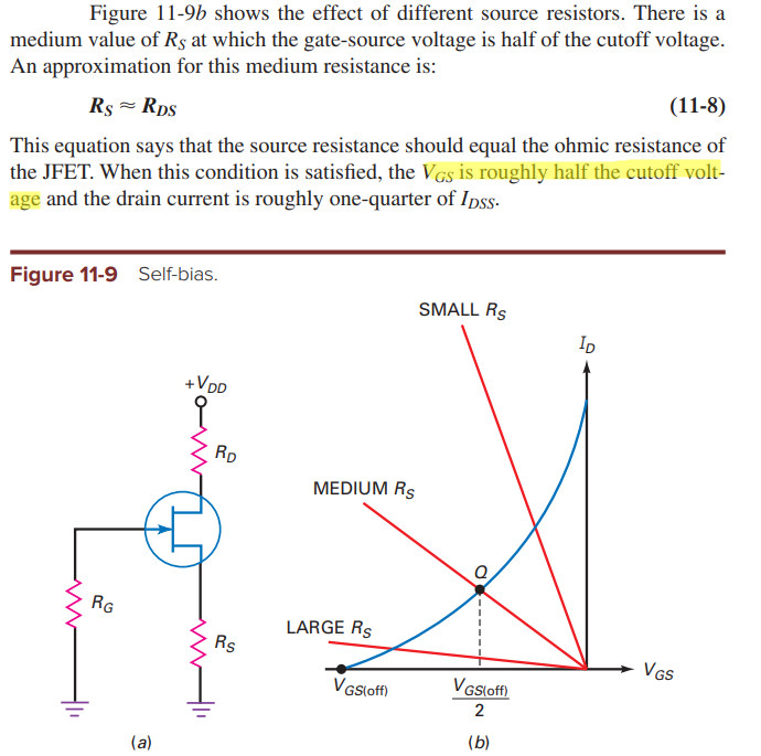
\$R_{DS}\$ is the resistance of jfet in the ohmic region. When the source resistor is matched to this value, my textbook seems to say that \$V_{GS}\$ will be half the cutoff/pinchoff voltage. Why is this so?
1 Answer
JFETs have a square-law current versus gate voltage.
thus: \$ I_d = \kappa \times (V_g - V_t)^2 \$
the derivative \$ \frac{d I}{d V_g} = \kappa \times [2 \times (V_g - V_t) ] \$
Which tells us what?
The ohmic resistance of the FET is the transconductance,
or \$ \frac{1}{d I / d V_g}\$
thus ohmic resistance = \$ \frac{1}{[\kappa \times 2 \times (V_g - V_t)]} \$
Is that "2" of use in understanding?
================================
becca what did you learn? does the math work?
-
\$\begingroup\$ I see that the curve is a parabola with vertex at cutoff voltage. Thus the normalized current will be 1/4 when the gate voltage is 1/2. I still don't see how making the source resistor value equal to the ohmic resistance fixes the Q point at (1/2, 1/4). Thank you :) \$\endgroup\$– acrossCommented Mar 11, 2020 at 16:59

