8
\$\begingroup\$

I have a project that's consuming 34 of a Xilinx Coolrunner II's macrocells. I noticed I had an error and tracked it down to this:

assign rlever = RL[0] ? 3'b000 :
                RL[1] ? 3'b001 :
                RL[2] ? 3'b010 :
                RL[3] ? 3'b011 :
                RL[4] ? 3'b100 :
                RL[5] ? 3'b101 :
                RL[6] ? 3'b110 :
                        3'b111;

assign llever = LL[0] ? 3'b000 :
                LL[1] ? 3'b001 :
                LL[2] ? 3'b010 :
                LL[3] ? 3'b011 :
                LL[4] ? 3'b100 :
                LL[5] ? 3'b101 :
                        3'b110 ;

The error is that rlever and llever are one bit wide, and I need them to be three bits wide. Silly me. I changed the code to be:

wire [2:0] rlever ...
wire [2:0] llever ...

so there were enough bits. However, when I rebuilt the project, this change costed me more than 30 macrocells and hundreds of product terms. Can anyone explain what I have done wrong?

(The good news is that it now simulates correctly... :-P )

EDIT -

I suppose I'm frustrated because about the time I think I start understanding Verilog and the CPLD, something happens which shows I clearly have no understanding.

assign outp[0] = inp[0] | inp[2] | inp[4] | inp[6];
assign outp[1] = inp[1] | inp[2] | inp[5] | inp[6];
assign outp[2] = inp[3] | inp[4] | inp[5] | inp[6];

The logic to implement those three lines occurs twice. That means that each of the 6 lines of Verilog consumes about 6 macrocells and 32 product terms each.

EDIT 2 - As per @ThePhoton's suggestion about the optimization switch, here is information from the summary pages produced by ISE:

Synthesizing Unit <mux1>.
    Related source file is "mux1.v".
    Found 3-bit 1-of-9 priority encoder for signal <code>.
Unit <mux1> synthesized.
(snip!)
# Priority Encoders                                    : 2
 3-bit 1-of-9 priority encoder                         : 2

So clearly the code was recognized as something special. The design is still consuming tremendous resources, however.

EDIT 3 -

I made a new schematic including only the mux that @thePhoton recommended. Synthesis produced insignificant resource usage. I also synthesized the module recommended by @Michael Karas. This also produced insignificant usage. So some sanity is prevailing.

Clearly, my use of the lever values is causing consternation. More To Come.

Final Edit

The design is no longer insane. I am not sure what happened, however. I made a lot of changes in order to implement new algorithms. One contributing factor was a 'ROM' of 111 15-bit elements. This consumed a modest number of macrocells but a lot of product terms - nearly all of those available on the xc2c64a. I look for this but had not noticed it. I believe my error was hidden by optimization. The 'levers' I'm talking about are used to select values from the ROM. I hypothesize that when I implemented the (busted) 1-bit priority encoder, ISE optimized away some of the ROM. That would be quite a trick, but it's the only explanation I can think of. This optimization reduced the resource usage markedly and lulled me into expecting a certain base-line. When I fixed the priority encoder (as per this thread,) I saw the overhead of the priority encoder and the ROM that had previously been optimized away and attributed this to the former exclusively.

After all this, I was good on macrocells but had depleted my product terms. Half of the ROM was a luxury, really, as it was just the 2's comp of the first half. I removed the negative values, replacing them elsewhere them with a simple calculation. This allowed me to trade macrocells for product terms.

For now, this thing fits into the xc2c64a; I've used 81% and 84% of my macrocells and product terms respectively. Of course, now I have to test it to ensure it does what I want...

Thanks to ThePhoton and Michael Karas for the assist. In addition to the moral support they lent to help me solve this, I've learned from the Xilinx document ThePhoton posted, and I implemented the priority encoder suggest by Michael.

\$\endgroup\$
8
  • \$\begingroup\$ doesn't every question mark there effectively imply a multiplexer, and structurally you've cascaded them as well? How many macro-cells did you expect it to take? \$\endgroup\$
    – vicatcu
    Commented Nov 11, 2012 at 4:30
  • \$\begingroup\$ I don't know how many macrocells the construct should consume. However, considering my project is currently consuming 34 macrocells including those two '1 bit' multiplexors, and that these are a small part of the project, I am surprised by this result. \$\endgroup\$
    – Tony Ennis
    Commented Nov 11, 2012 at 4:39
  • \$\begingroup\$ What tool are you using? \$\endgroup\$
    – The Photon
    Commented Nov 11, 2012 at 4:44
  • \$\begingroup\$ Xilinx's ISE... \$\endgroup\$
    – Tony Ennis
    Commented Nov 11, 2012 at 4:45
  • \$\begingroup\$ In the code in your edit, I think you want | instead of ||. \$\endgroup\$
    – The Photon
    Commented Nov 11, 2012 at 15:28

2 Answers 2

7
\$\begingroup\$

The code you show is essentially a priority encoder. That is, it has an input of many signals, and its output indicates which of those signals is set, giving priority to the left-most set signal if more than one is set.

However, I see conflicting definitions of the standard behavior for this circuit in the two places I checked.

According to Wikipedia, the standard priority encoder numbers its inputs from 1. That is, if the least significant input bit is set, it outputs 1, not 0. The Wikipedia priority encoder outputs 0 when none of the input bits are set.

Xilinx's XST User Guide (p. 80), however, defines a priority encoder closer to what you coded. The inputs are numbered from 0, so when the input's lsb is set it gives a 0 output. However, the Xilinx definition gives no spec for the output when all input bits are clear (Your code will output 3'd7).

The Xilinx user guide, of course, will determine what the Xilinx synthesis software is expecting. The main point is that a special directive (*priority_extract ="force"*) is required for XST to recognize this structure and generate optimal synthesis results.

Here's Xilinx's recommended form for an 8-to-3 priority encoder:

(* priority_extract="force" *)
module v_priority_encoder_1 (sel, code);
input [7:0] sel;
output [2:0] code;
reg [2:0] code;
always @(sel)
begin
    if (sel[0]) code = 3’b000;
    else if (sel[1]) code = 3’b001;
    else if (sel[2]) code = 3’b010;
    else if (sel[3]) code = 3’b011;
    else if (sel[4]) code = 3’b100;
    else if (sel[5]) code = 3’b101;
    else if (sel[6]) code = 3’b110;
    else if (sel[7]) code = 3’b111;
    else code = 3’bxxx;
end
endmodule

If you can rearrange your surrounding logic to let you use Xilinx's recommended coding style, that's probably the best way to get a better result.

I think you can get this by instantiating the Xilinx encoder module with

v_priority_encoder_1 pe_inst (.sel({~|{RL[6:0]}, RL[6:0]}), .code(rlever));

I've nor'ed together all bits of RL[6:0] to get an 8th input bit that will trigger the 3'b111 output when all RL bits are low.

For the llever logic, you can probably reduce the resource usage by making a modified encoder module, following the Xilinx template, but requiring only 7 input bits (your 6 bits of LL plus an additional bit that goes high when the other 6 are all low).

Using this template assumes the version of ISE you have is using the XST synthesis engine. It seems like they change synthesis tools on every major rev of ISE, so check that the document I linked actually corresponds to your version of ISE. If not, check the recommended style in your documentation to see what your tool expects.

\$\endgroup\$
4
  • \$\begingroup\$ Thanks, that will take some time to digest. My ISE is using XST though I don't know which version. \$\endgroup\$
    – Tony Ennis
    Commented Nov 11, 2012 at 5:45
  • \$\begingroup\$ The key is having the (* priority_extract="force" *) and probably also explicitly including the don't-care output even though you cover every possible input. (Without it, XST is probably trying to generate a complete look-up table, which is why so many product terms) Try adding the don't care option first. If it doesn't work, then try using the Xilinx boilerplate exactly. \$\endgroup\$
    – The Photon
    Commented Nov 11, 2012 at 5:57
  • \$\begingroup\$ I implemented a complete rip of the code above and did not get an improved result. The ISE summary pages indicate a MUX was recognized, though the recognition wasn't as strong as for other constructs. I'll post the relevant information in a few minutes. \$\endgroup\$
    – Tony Ennis
    Commented Nov 11, 2012 at 15:25
  • \$\begingroup\$ edit - ignore the comment above about 'strong recognition' - it's there, I just missed it last night; I redid the work and reality is operating correctly. \$\endgroup\$
    – Tony Ennis
    Commented Nov 11, 2012 at 15:51
6
\$\begingroup\$

ThePhoton's answer is an excellent one. I would like to add some additional information here for your consideration. This stems from the fact that even though we have state of the art fancy FPGA and CPLD devices using HDLs and systhesis tools it can be informative to look closely at things designed years ago. Stay with me while I walk through this to my recommendation at the end.

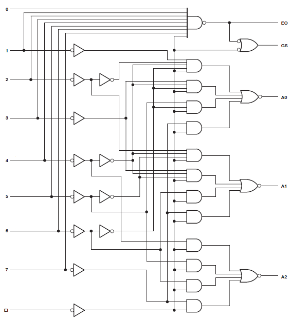
There are discrete logic parts that perform the priority encoding function. The logic implemented by these parts has been around for a long time when it was essential to reduce the number of transistors to a bare minimum. You can search on the web for logic parts with generic part numbers such as 74HC148 or MC14532B to find data sheets that include equivalent logic diagrams for these parts. The diagram below is one example taken from the TI data sheet for the 74HC148 part.

enter image description here

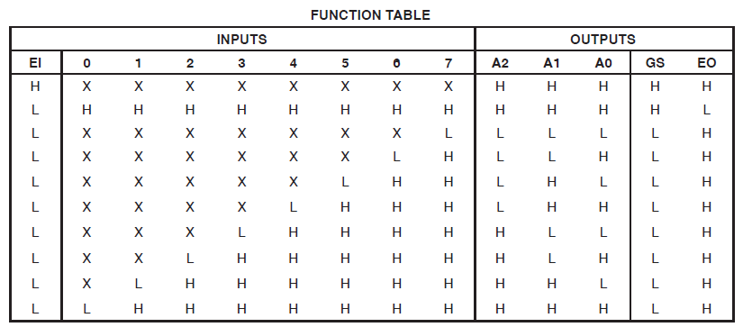
This logic implements the following truth table (taken from the same data sheet):

enter image description here

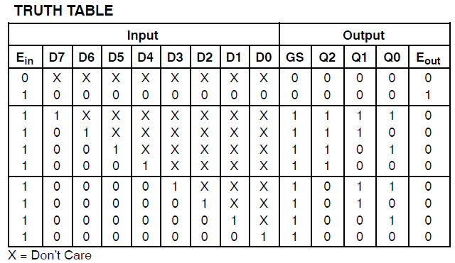
Note that the above part family uses low active input signals. Another data sheet for the ON Semiconductor MC14532B part shows a truth table for the encoder function using active high input signals similar to your Verilog example.

enter image description here

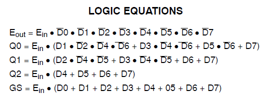
The same data sheet shows the logic equations for the MC14532B as follows:

enter image description here

You may want to consider coding similar equations directly into your Verilog code to see how it compares with your present example. It is highly likely to result in a much more favorable result.

\$\endgroup\$
4
  • \$\begingroup\$ Thanks, I will do so. This problem is killing me. I believe it was synthesizing more efficiently previously. And then I Changed Something. /selfbonk \$\endgroup\$
    – Tony Ennis
    Commented Nov 11, 2012 at 14:19
  • \$\begingroup\$ Thanks, I have implemented it. It did not make a material difference, unfortunately. \$\endgroup\$
    – Tony Ennis
    Commented Nov 11, 2012 at 15:14
  • \$\begingroup\$ Nice answer. Let's Tony see just how many product terms it should need to implement this logic. Tony, if you use either Xilinx's boilerplate or Michael's equations, and you are still generating hundreds of product terms, then you need to look for a subtle change somewhere else in your code that might have caused the problem; or else look very carefully at the synthesis log file to see if something is happening that you don't expect. \$\endgroup\$
    – The Photon
    Commented Nov 11, 2012 at 15:25
  • \$\begingroup\$ I agree with @ThePhoton completely. I have hosed something. I'm as sure as I can be that this used to work - I didn't even notice the consumption it was so small. Oh well, it's a good excuse to start understanding more of the Summary information. \$\endgroup\$
    – Tony Ennis
    Commented Nov 11, 2012 at 15:43

Your Answer

By clicking “Post Your Answer”, you agree to our terms of service and acknowledge you have read our privacy policy.

Not the answer you're looking for? Browse other questions tagged or ask your own question.