1
\$\begingroup\$

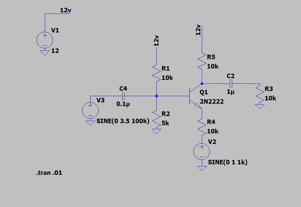
I am trying to build an AM radio transmitter. I have built a Colpitts oscillator with a 7 Vpp output and an audio stage with a 1 Vpp output. I am trying to build the amplitude modulation stage I am using a circuit like this.

enter image description here

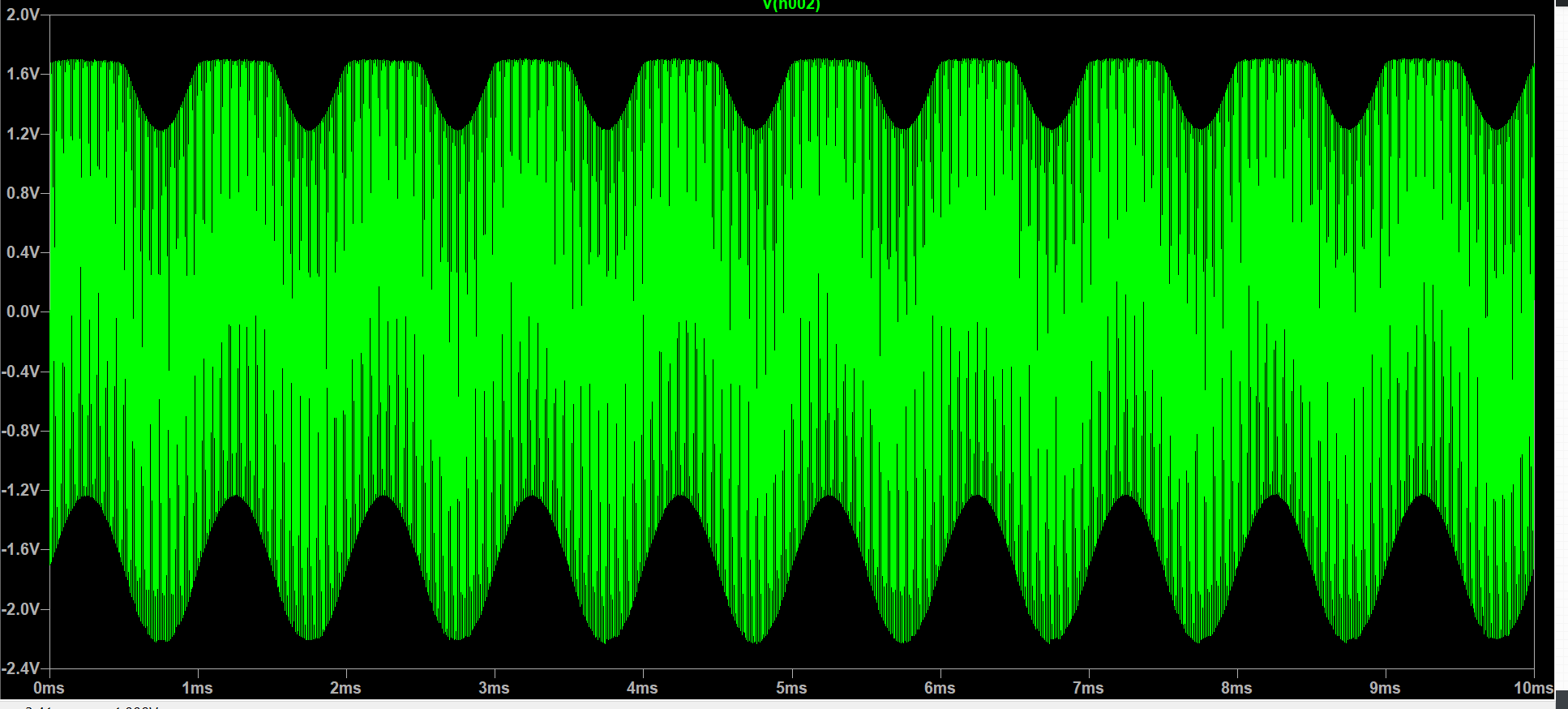
But my output on R3 looks like a mixer signal instead of a modulated one and is getting clipped. what is causing it to do this? And what would be a solution to get amplitude modulation? Any resources or help would be appreciated. I would like the amplitude modulation stage to not use IC's if possible.

enter image description here

====================================================================

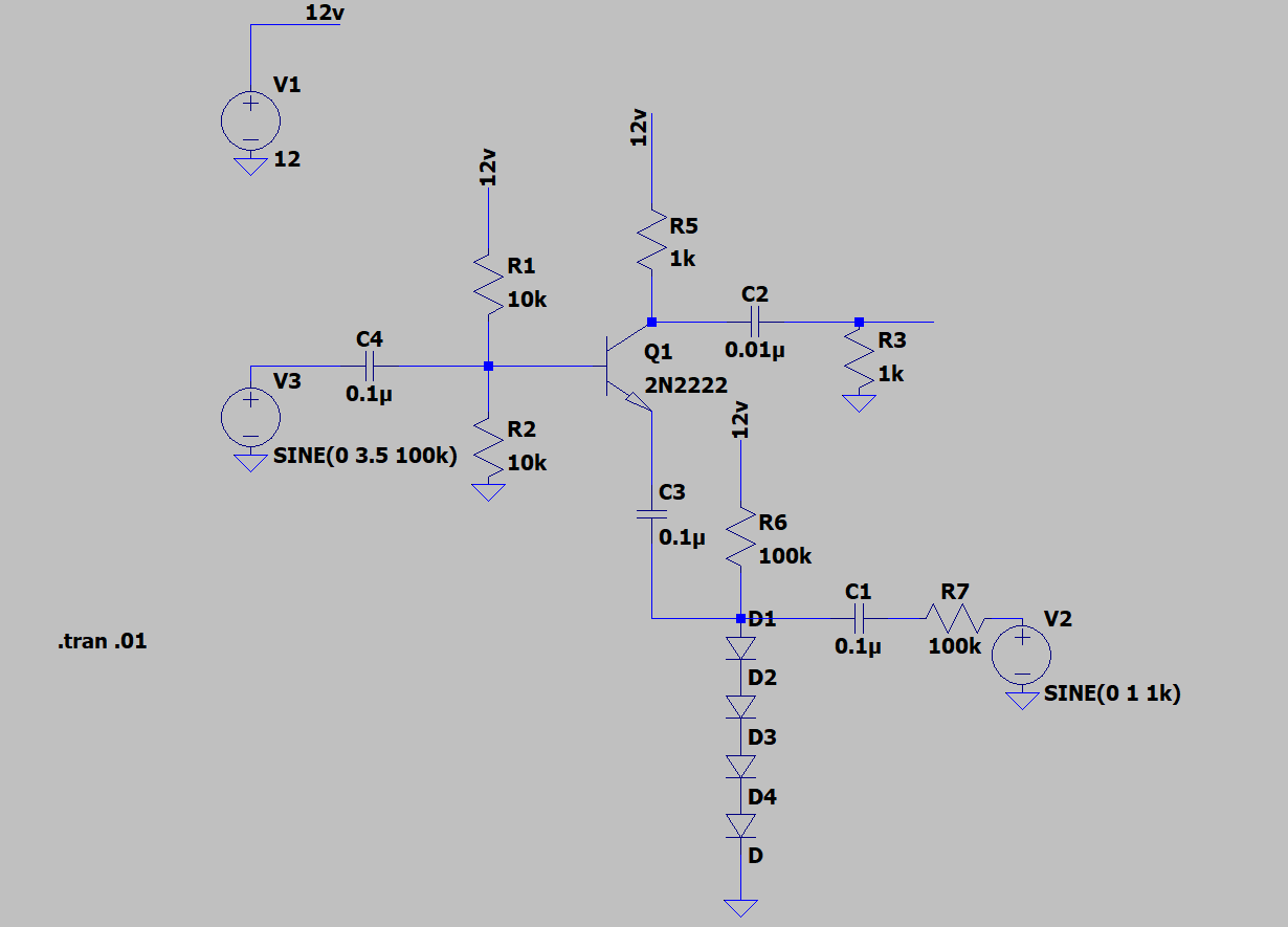
Ok here is my new schematic with a varying resistive network (as suggested below)

I am still not seeing the intended results, any ideas?

enter image description here

\$\endgroup\$

2 Answers 2

0
\$\begingroup\$

Your current circuit https://i.sstatic.net/Bu4mR.png has even no DC path for the current of the transistor. It cannot work. Using diodes as variable resistors is good idea at millivolt levels, but at several volts - no hope. Analog multiplier would be better but only at well below 1MHz.

Actually your 1st attempt is a kind of AM modulator. The clipping level depends on audio signal. But filtering the distortion components off can be impossible in your case. AM by varying the operating voltage of a distorting amp IS widely used, but the distortion method must be selected for making possible to extract the wanted frequency components . The working amp is of class C.

Try something else. Colpitts, Hartley etc.. traditional oscillator circuits were big inventions when no modern high gain components were available. Carefully calculated oscillator circuits were a must to have something usable even at few MHz.

Today the situation is different. An oscillator can work acceptably with pure experimental component values, maybe only after recalling that in a CB radio there were approximately this looking inductors and capacitors.

If the oscillator has no amplitude stabilization circuit for clean sinewave output its output amplitude grows until the limit of distortion is reached. That limit depends on the operating voltage and it makes amplitude modulation easy. You simply swing the operating voltage of an oscillator around some average DC voltage. A classical version of this is to feed the operating voltage of the oscillator through the secondary of a transformer. Then an audio signal is fed to the primary.

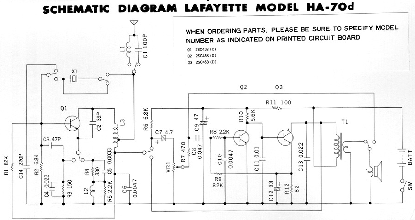
No transformer is actually needed, simply have inductive load for an audio amp and feed the DC supply for the oscillator through the same inductor. It's used in this ingenious vintage CB walkie talkie. In receive operation the same inductor is a part of the loudspeaker transformer (T1):

enter image description here

The image is taken from this story: http://analogdial.com/AstroCommander/Commander2.html

The leftmost transistor is super-regenerative AM detector for receive and for transmitting it changes to crystal stabilized oscillator with AM by voltage swinging. I must admit that the designer of this machine really knew something.

If you have an amp IC which has say plusminus 12V dual power supply you can connect your oscillator between the IC output and minus 12V rail. Then you'll have 12V rest voltage for the oscillator. An emitter follower + some RC lowpass filtering would be needed to isolate the amp from the RF circuits.

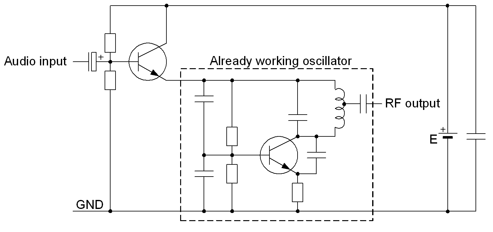
ADD due a comment: here's one elementary possibility.

enter image description here

The battery voltage E must be high enough to cover the idle state DC feed of the oscillator plus the peak audio voltage. Inductor and transformed based modulators do not need that extra DC over the idle state feed, but the power requirement is still the same.

The RF output is taken from the coil tap, output directly from the collector can make the frequency depend too much on the load variations or even suffocates the oscillation. Generally only a portion of the reactive power in the resonant circuit can be taken out. If one needs more power, he should add a linear amp behind this or have a class C amp with modulator.

\$\endgroup\$
10
  • \$\begingroup\$ I built the audio amp and the Colpitts oscillator my self, so they are very weak. I tried driving the oscillator from the amp but I think it is too weak. It sounds to me like I had the right idea with the first circuit, I was actually tinkering around with it and got something like AM out. Would you suggest using the circuit I originally designed? \$\endgroup\$
    – Riley
    Commented Mar 21, 2020 at 23:01
  • \$\begingroup\$ No. Feed your oscillator with DC from an emitter follower which has voltage divider making good DC to the base. Connect the audio to the base with a capacitor => you'll have swinging DC operating voltage for your oscillator. Have a few hundred pF capacitor from the emitter to GND, too in parallel with the oscillator. \$\endgroup\$
    – user136077
    Commented Mar 21, 2020 at 23:13
  • \$\begingroup\$ Perfect, that is now modulating the oscillations. Now I have about a 4 Vpp AM modulated wave. I'm struggling now to pick it up on a receiver. Any suggestions? Should I put an amp on the output of the oscillator? \$\endgroup\$
    – Riley
    Commented Mar 22, 2020 at 0:06
  • \$\begingroup\$ if I add a linear amp, should it go after the oscillator, where you have labeled RF out? \$\endgroup\$
    – Riley
    Commented Mar 22, 2020 at 0:14
  • \$\begingroup\$ Linear amp should be connected to RF out in the right edge. BEWARE: The oscillator with its coil and modulator should be in metal shield to avoid making an incredibly unpredictable complex oscillating system. Another thing: Do not make any radio broadcastings without a legal license which is valid in your country. There's many jails waiting new inhabitants. I wrote this because I do not want to be one as an assistant. \$\endgroup\$
    – user136077
    Commented Mar 22, 2020 at 0:23
1
\$\begingroup\$

You are doing well thus far. You want to vary the gain, not the DC component.

The gain is ratio of Rcollector / Remitter.

Rcollector is R5 || R3.

Remitter is (R4 + reac), where 1mA thru Q1 makes reac be 26 ohms, and 0.1mA makes reac be 260 ohms (its the gradient of the diode junction, or the transconductance).

======== edited 3/21/2020 with details on variable-gain components ==========

these components are based on your ORIGINAL circuit

One way to vary the gain is with 4 diode in series, biased at 0.1 milliamp.

Each diode is nominally 260 ohms ( for 5% or 16% changes in current), thus the total is 4 * 260 = 1,040 ohms, for small signal operation. This means with a few millivolts change in the diode voltage, the delta_V/delta_I of each diode will be (approximately) 260 ohms.

Now we need that 0.1 milliAmp DC biasing. We can view a 0.1 ma current as needing 10,000 ohms per volt. We have about 0.5 volts DC per diode, thus 2.0 volts across the 4. That leaves (12 - 2) = 10 volts across the resistor we'll add between top of diode chain and your +12 volts.

A 100,000 ohm resistor to +12volts provides the biasing.

To vary the resistance of the diodes from our nominal 1,040 ohms, we must vary the current using the modulation voltage. Connect a series RC network from the top diode to the modulation voltage. For low distortion, only change the current by +-10% at most. A 0.1ucap in series with 100,000 ohm, and ONE volt modulation, will inject 10uA varying current, thus only 10% change in diode chain (dynamic, small signal) resistance and thus 10% change in gain.

Now you need to have this varying-resistance network (4 diodes, 2 resistors, 1 cap) be able to vary the amplifier gain.

Add a 2nd capacitor from top of the diode chain to your emitter.

ohhhh reduce the collector to 1,000 ohms.

===================================== edit =========

Thank you for reminding me about the modulation voltage.

regarding the original circuit:

1) remove the modulation voltage from being in series with the 10,000 ohm emitter resistor

2) connect the modulation voltage to that series RC (DC blocked) network to the top of the 4 diodes.

\$\endgroup\$
5
  • \$\begingroup\$ If I lower the gain, I get a signal that looks like I am adding the carrier and audio signal together, instead of multiplying the amplitudes. To fix this problem, do I need a bandpass filter? or a new circuit entirely? \$\endgroup\$
    – Riley
    Commented Mar 21, 2020 at 0:02
  • \$\begingroup\$ Lowering the gain fixes the clipping however, I get a signal that looks like I am adding the carrier and audio signal together, instead of multiplying the amplitudes. I am thinking of the symmetric signal (about x) that you see in textbooks when I refer to amplitude modulation, but will this superposition of signals (that I see in my picture) work? \$\endgroup\$
    – Riley
    Commented Mar 21, 2020 at 0:15
  • \$\begingroup\$ I think I got lost in your post, mind putting a schematic up and explaining it so we are both on the same page? Thanks \$\endgroup\$
    – Riley
    Commented Mar 21, 2020 at 16:44
  • \$\begingroup\$ Could you explain more what you mean by "feed in the modulation"? where should that 10k go exactly and is the 1uf capacitor the one on the collector? \$\endgroup\$
    – Riley
    Commented Mar 21, 2020 at 17:05
  • \$\begingroup\$ what is the modulation voltage in my case? My guess is V2 \$\endgroup\$
    – Riley
    Commented Mar 21, 2020 at 20:26

Your Answer

By clicking “Post Your Answer”, you agree to our terms of service and acknowledge you have read our privacy policy.

Not the answer you're looking for? Browse other questions tagged or ask your own question.