0
\$\begingroup\$

I built the following circuit to filter noisy pulses from a inductive tachometer pickup. The first opamp (U4D) acts as a peak detector. The second opamp (U4C) is a comparator which uses the output from the first as a reference voltage. The positive feedback on the comparator is for hysteresis.

enter image description here

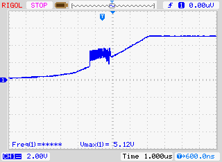
I am getting a lot of noise on the output of the comparator. All of the technical articles I have read suggesting adding hysteresis (which I have already done) or using an actual comparator IC instead. Are there any other ways that I may be able to salvage this circuit?

enter image description here

\$\endgroup\$
8
  • \$\begingroup\$ You have forward feedback but it doesn't look like it is set up for reliable, predictable hysteresis to me since you are feeding your signal positive feedback to the same input. That means your hysteresis depends on your input level. \$\endgroup\$
    – DKNguyen
    Commented Mar 24, 2020 at 22:39
  • \$\begingroup\$ @DKNguyen, what is wrong with my hysteresis setup? \$\endgroup\$ Commented Mar 24, 2020 at 22:40
  • \$\begingroup\$ @DKNguyen, I am using the non-inverting setup shown here e2e.ti.com/blogs_/archives/b/thesignal/archive/2013/01/28/… \$\endgroup\$ Commented Mar 24, 2020 at 22:41
  • \$\begingroup\$ Have you just tried reducing the 300K? \$\endgroup\$
    – DKNguyen
    Commented Mar 24, 2020 at 22:49
  • \$\begingroup\$ Looks like you’ve built an oscillator. Replace R1 with two resistors, one to each rail. \$\endgroup\$ Commented Mar 24, 2020 at 22:53

2 Answers 2

2
\$\begingroup\$

enter image description here

When comparator U4C output goes high (caused by the "A" signal from the first stage rising through the threshold set at "B") there is a reaction that lifts input "C" at U4D a little higher.

Lifting "C" higher causes the precision rectifiers output level (U4D) to rise and that, in turn causes the "B" signal to rise. That, in turn causes U4C's comparator output to switch back low.

At the start of the sentences above I said U4C output went high but, that caused a chain of events that ended up with it going low pretty much straight away afterwards.

Do you see the problem? The problem is that the actual input ("C") to U4D can be manipulated by the output of U4C and that is because that TACH1 input is fed via R4, a 10 kohm resistor. If that resistor wasn't there i.e. it were a short AND the output impedance of the input voltage at TACH1 were very low then this wouldn't happen.

\$\endgroup\$
2
  • \$\begingroup\$ I think I understand. I could possible solve this by adding an opamp buffer just to the right of C9? Is there another good way to isolate those two sections of the circuit? \$\endgroup\$ Commented Mar 25, 2020 at 0:36
  • \$\begingroup\$ I'd arrange U4C so that the hysteresis was not acting on the input signal but on the output of the peak detector. This inverts the output of course. \$\endgroup\$
    – Andy aka
    Commented Mar 25, 2020 at 8:10
0
\$\begingroup\$

I expect your slewrate is too slow to push the 2nd opamp out of the linear region. So the circuit oscillates.

\$\endgroup\$

Your Answer

By clicking “Post Your Answer”, you agree to our terms of service and acknowledge you have read our privacy policy.

Not the answer you're looking for? Browse other questions tagged or ask your own question.