1
\$\begingroup\$

I am having troubles trying to translate when finding a transfer function of an active filter is it in a 'Close loop' or 'Open loop' state?

When finding the transfer function of these active op-amps how come we don't include the characteristics of the op amp itself?

For example a Op-Amp has an Op-loop gain I would imagine you need to include that in your transfer function otherwise you could use any op amp/disregard any op amp?

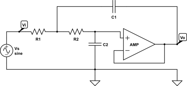
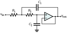
Example: Sallen-Key Butterworth Filter of 2nd Order

$$ H(s) = \frac{1}{C_1 C_2 R_1 R_2 s^2 + C_2 R_1 s + C_2 R_2 s + 1}$$

enter image description here

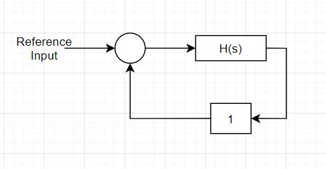
Its confusing as the OP-amp has a feedback of 1.

Closed Loop:

enter image description here

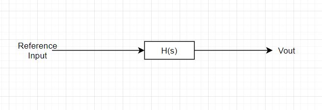
Open Loop:

enter image description here

\$\endgroup\$
6
  • \$\begingroup\$ Its confusing as the OP-amp has a feedback of 1. There is another feedback path, through C1. Why open loop vs closed loop? The circuit has a transfer function H(s). That the circuit creates that function using internal feedback is irrelevant (for H(s) ). Only if you want to make a block diagram of the circuit including all feedback loops should you also draw these loops. \$\endgroup\$ Commented Apr 1, 2020 at 17:46
  • \$\begingroup\$ The reason why I am planning on discretizing the plant and I have no idea if its an open loop or close loop state. Ah fair it does have another path \$\endgroup\$
    – Leoc
    Commented Apr 1, 2020 at 17:51
  • \$\begingroup\$ If there is a denominator, and not just some constant, there is feedback. What you refer to as "feedback of 1" is wrong to think that the numerator represents the feedback, since the expression is V(out)/V(in), that is, you multiply the denominator of the transfer function with V(out), and the numerator with V(in). \$\endgroup\$ Commented Apr 1, 2020 at 17:52
  • \$\begingroup\$ I dont think the numerator represented the feedback, I just said that due to looking at the op-amp itself. It does have a feedback of 1. The negative terminal has a path to the output \$\endgroup\$
    – Leoc
    Commented Apr 1, 2020 at 17:54
  • \$\begingroup\$ and I have no idea if its an open loop or close loop state Is there a loop through which a signal can travel back in the direction of the input? Then the loop is closed. Open loop is usually only considered in analysis, the loop is opened and then examined if the loop would be stable if is was closed. \$\endgroup\$ Commented Apr 1, 2020 at 17:55

3 Answers 3

3
\$\begingroup\$

I am having troubles trying to translate when finding a transfer function of an active filter is it in a 'Close loop' or 'Open loop' state?

Of course, the filter function is available in a closed-loop condition only. It is the frequency-variable feedback network which gives the desired filter characteristic.

When finding the transfer function of these active op-amps how come we don't include the characteristics of the op amp itself?

It is common practice to assume idealized opamps only (infinite gain, no frequency dependent gain). Of course, this simplification causes errors in the transfer characteristic - however, this is acceptable as long as the operating frequency range is limited to a region where other uncertainties (parts tolerances) are dominating. Of course, this means that opamp based filters are used not in the upper MHz range (where opamp non-idealities play a remarkable role).

Please note, that there are many, many different lowpass circuit alternatives which ALL would have the same transfer function in practice (reality) - under the assumption of IDEAL opamps. The difference between these alternatives can be revealed only for REAL opamps. In this context, it is important if the opamp is used as a fixed-gain positive amplifier (Sallen-Key) or as a high-gain amplifier (multi-feedback) or as an integrator (state-variable structures). All these alternatives have different sensitivities against opamp non-idealities.

For example a Op-Amp has an Op-loop gain I would imagine you need to include that in your transfer function otherwise you could use any op amp/disregard any op amp?

Of course, theoretically we could include the open-loop gain of the amplifier into the overall transfer function....but for which purpose? To slightly improve the accuracy of the function ? The price for it would be a very complicated transfer function which is very hard to use for practical realisations.

Remark: There are studies which show how the frequency-dependent open-loop gain of an opamp can be exploited - together with a pure resistive feedback network without external capacitors - for realizing active filters ("R-filter). However, as a severe drawback, it is necessary to know the exact open-loop gain opamp characteristic, which has very large tolerances. Buth these filters have no practical relevance....

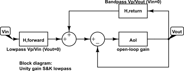
Comment 1: Of course, it is possible to create a block diagram in the classical form with a feedback block (and with a summing junction at the input) and a block with the opamps open-loop gain - but for which purpose?

Comment 2: Actually, as an advantage of block diagram visualization, it is very easy to see HOW the S&K lowpass works: There is a passive lowpass (Hforward) with a bad quality factor (pole-Q) Qp<0.5.

However, in the "critical" frequency region (exactly at the pole frequency) the bandpass in the feedback path enhances the amplitude of the lowpass because the bandpass has the same pole frequency (zero phase shift, positive feedback effect). This effect produces a larger Q value (Example: Qp=0.7071 for a Butterworth response).

EDIT: Block diagram: Both passive transfer functions (lowpass, bandpasss) are derived from the original circuit. Vp is the signal voltage at the positive (non-inverting) opamp input terminal.
schematic

simulate this circuit – Schematic created using CircuitLab

\$\endgroup\$
15
  • \$\begingroup\$ Thank you for the read, put a lot of things together. To answer your comment, I was about to say. The reason I asked about this is because I want to discretize the Butter worth filter and I dont know which way to do it either using, Tusin, ZoH, etc. I thought having it in block diagram form would help me decide which method to use. For curiosity sake assuming ideal op amps. Is that block diagram correct if not what would it look like? \$\endgroup\$
    – Leoc
    Commented Apr 1, 2020 at 19:51
  • \$\begingroup\$ It is not a simple task to create a block diagram....give me some time (until tomorrow). \$\endgroup\$
    – LvW
    Commented Apr 1, 2020 at 19:57
  • \$\begingroup\$ Not a problem. Appreciate the help regardless. Any thought on discretizing the Butter worth filter using ZoH or Tustin? \$\endgroup\$
    – Leoc
    Commented Apr 1, 2020 at 19:58
  • \$\begingroup\$ Please explain: ZoH ...Tustin? \$\endgroup\$
    – LvW
    Commented Apr 2, 2020 at 7:27
  • \$\begingroup\$ Zero Order Hold, Tustin method from transforming continuous to discrete. Thank yo so much for the block diagram \$\endgroup\$
    – Leoc
    Commented Apr 2, 2020 at 14:01
2
\$\begingroup\$

@LvW Answer is just perfect.

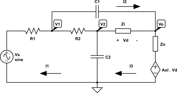
But just for fun, I think you can accomplish your task. From this base schematic:

schematic

simulate this circuit – Schematic created using CircuitLab
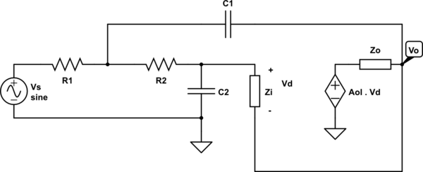
You can model the amplifier as a input impedance and controlled voltage source in series with an output impedance.

schematic

simulate this circuit

Of source we can rearrange the circuit to become more easy to visualize its meshes and nodes:

schematic

simulate this circuit

Now, I have used mesh analysis (tough I tried with node and didn't like were it was going) to obtain the filter transfer function (after many more hours than I thought it would be necessary and many possible mistakes):

\$H(s)= \frac{A_{ol}(s)Z_{i}(s)+Z_o(s)[1+s C_1 (R_2+Z_i(s))]}{A_{ol}Z_i(s)[s^2C_1C_2 R_1 R_2+s C_2(R_1+R_2)+1] + s^2C_1C_2 \frac{R_1R_2Z_o(s)Z_i(s)}{R_1//R_2//Z_o(s)//Z_i(s)}+ s[ C_2(R_1+R_2)(Z_o(s)+Z_i(s)) + C_1((Z_i(s)+R_1)(Z_o+R_2)] + (R_1+R_2) +Z_o(s) + Z_i(s)}\$

Curiously, but not a proof per se, if you rearrange terms to only have \$1/Z_i\$ and \$1/A\$ format and take the limit of \$Z_0 \rightarrow 0\$, \$Z_i \rightarrow \infty\$ and \$A_{ol} \rightarrow \infty\$ (only the terms with \$Z_i\$ \$A\$ are nonzero) it will become the given original and simpler transfer function.

\$H(s)= \frac{A_{ol}(s)Z_{i}(s)}{s^2C_1C_2 R_1 R_2 A_{ol}Z_i(s)+ s C_2 (R_1+R_2) Z_i(s)A_{ol}(s) + Z_i(s)A_{ol}(s)} = \frac{1}{s^2C_1C_2 R_1 R_2 + s C_2 (R_1+R_2) + 1}\$

I think this may be partially useful just to show that there isn't a simple block transfer multiplication, but it will take into account very relevant limitations of the amplifier. Any additional limitation will imply that linear operators and transfer functions can't properly describe it.

Since this took me a lot more hours than I expected I am planning to write another one or a edit to this one with a very different approach exploiting a similar idea that @LvW diagrams leads to, unfortunately yesterday the diagram was not uploaded yet.

Edit 1 : Following @LvW suggestion, we can model the amplifier as \$A_{ol}(s) = G\frac{\omega_0^2}{s^2+2 \xi \omega_0s +\omega_0^2}\$ and \$Z_i(s)=R_i\$ and \$Z_o(s)=R_o\$. Curiously, after doing this and finding some 2 algebraic manipulation errors, its not hard to separate the amplifier gain characteristic indeed, as corrected above. The new transfer function with the second order filter is now:

\$H(s)= \frac{G R_{i}\omega_0^2+(s^2+2\xi\omega_0+\omega_0^2)R_o[1+s C_1 (R_2+R_i)]}{G\omega_0^2R_i[s^2C_1C_2 R_1 R_2+s C_2(R_1+R_2)+1] + (s^2+2\xi\omega_0+\omega_0^2)[s^2C_1C_2 \frac{R_1R_2R_oR_i}{R_1//R_2//R_o//R_i}+ s[ C_2(R_1+R_2)(R_o+R_i) + C_1(R_i+R_1)(R_o+R_2)] + (R_1+R_2) +Z_o(s) + Z_i(s)]}\$

Which is truly an horrific expression.

\$\endgroup\$
2
  • \$\begingroup\$ You can assume with good precision that \$Z_i(s) \approx R_i\$ just as \$Z_o(s) \approx R_o\$. \$\endgroup\$
    – Trevor
    Commented Apr 2, 2020 at 12:32
  • 1
    \$\begingroup\$ Trevor..I wonder how the transfer function would look like if you replace Aol(s) with a second-order gain function... ..I think, this would convince the questioner that it makes no sense to incorporate all the non-idealities of the opoamp into the filter function. \$\endgroup\$
    – LvW
    Commented Apr 2, 2020 at 12:52
2
\$\begingroup\$

When finding the transfer function of these active op-amps how come we don't include the characteristics of the op amp itself?

Generally you want to operate at frequency/gain underneath the gain bandwidth product. That way the op-amp dynamics don't come into play.

\$\endgroup\$
5
  • \$\begingroup\$ Michael....are you sure? I have some experience with gyrator applications for active filters. However, I have never seen that somebody exploits the frequency-dependent gain of the opamps for this purpose. I rather think, active inductors and FDNR`s are designed assumng IDEAL opams only.. \$\endgroup\$
    – LvW
    Commented Apr 2, 2020 at 14:42
  • \$\begingroup\$ @LvW "frequency/gain underneath the gain bandwidth product" he does that exactly to avoid reaching the limit of the amp op. \$\endgroup\$
    – jDAQ
    Commented Apr 2, 2020 at 15:59
  • \$\begingroup\$ jDAQ..you misunderstood something. My comment was to Michaels claim: "...realizing impedances ..the opamps integrator like response is used". That means, he thinks that the real opamp`s frequency-dependent gain would be exploited - and this is not the case. \$\endgroup\$
    – LvW
    Commented Apr 2, 2020 at 16:24
  • \$\begingroup\$ @LvW Excuse my mistake, I misremembered. You are correct, I have edited the response to fix this. \$\endgroup\$ Commented Apr 3, 2020 at 21:19
  • \$\begingroup\$ Michael...no problem....misunderstandings cannot be avoided \$\endgroup\$
    – LvW
    Commented Apr 4, 2020 at 8:33

Your Answer

By clicking “Post Your Answer”, you agree to our terms of service and acknowledge you have read our privacy policy.

Not the answer you're looking for? Browse other questions tagged or ask your own question.