14
\$\begingroup\$

I'm trying to get what amounts to a knock indication into a microcontroller input from a piezo sensor. It's looking fairly good now at the fifth iteration, and about ready to provide digital levels for input to a 3v3 MCU.

I started with an "instrumentation amp" but changed that to a charge amplifier as suggested by @Circuitfantasist. Also based on a comment he made elsewhere, I then changed the hacked 'rectifier' I had before into a standard "precision rectifier".

The third change was the addition of the RC pair and a diode to ensure the output stays high for a "little while" after the strike is first registered.

The fourth change was the addition of the two-transistor schmitt trigger on the output. Change five replaced the discrete schmitt with an IC comparator using positive feedback for hysteresis and having an open collector output to get the levels set up right for the MCU.

Here's the circuit now:

schematic

simulate this circuit – Schematic created using CircuitLab

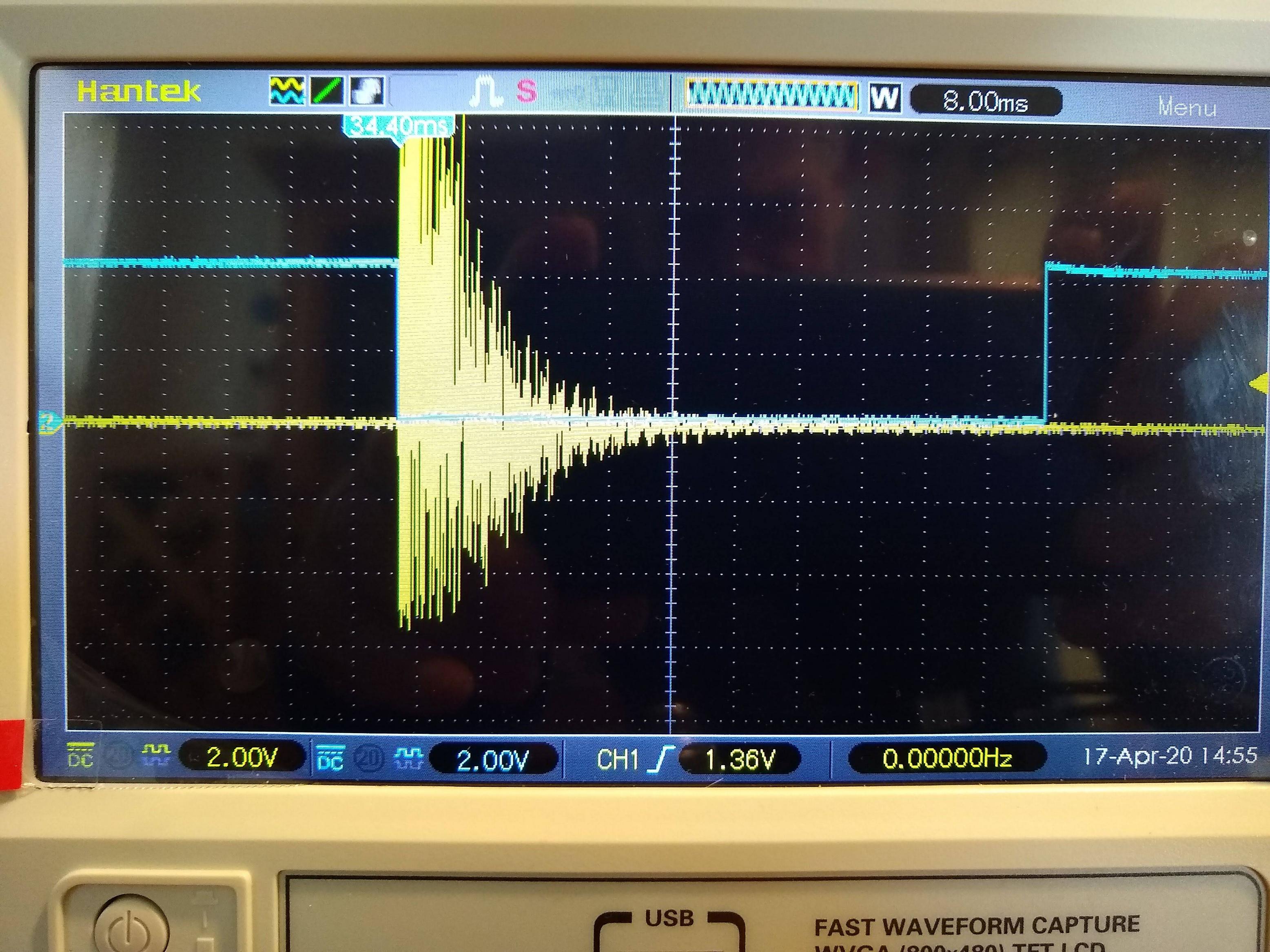
It seems to work quite well. Yellow is the input signal raw from the piezo device (the signal is essentially the ringing sound of a chunk of steel being hit with a hammer), blue is the output. It's intended to trigger an interrupt with the falling edge:

enter image description here

From here, I think it's ready to have the final output put into an MCU. If that actually changes anything, I'll update here.

As a side note, I learned a lot about verifying the 9V battery you're using is actually still good. This thing oscillated in most curious ways for a while, and I eventually realized that it was the supply rails drooping when things changed state, and that in turn was because my little PP3 9V battery was essentially dead, and putting out about 8.3V with no load. This also reduced the noise on the signal quite a bit. Oh, the joy of learning :)

\$\endgroup\$
12
  • 2
    \$\begingroup\$ Consider using a high-pass filter or differentiator -- this would remove any unwanted offset voltage drift from the pizeo, preventing the output amplifier from saturating, while passing the signal you're interested in. \$\endgroup\$
    – MarkU
    Commented Apr 11, 2020 at 6:34
  • 3
    \$\begingroup\$ The usual solution is the so-called "charge amplifier" that is actually a "current integrator". In contrast to your solution (instrumentation amplifier), its input impedance is almost zero (short connection). This depresses the stray capacitance. \$\endgroup\$ Commented Apr 11, 2020 at 8:30
  • 1
    \$\begingroup\$ @Toby Eggitt, I perfectly understand you... This extremely simple device consists only of an op-amp and a capacitor connected between the output and inverting input. The piezo sensor behaves as a charged capacitor. It is shorted by the virtual ground and its charge is transferred to the feedback capacitor. The op-amp copies the voltage across this capacitor so the op-amp output voltage is proportional to the input voltage. All undesired capacitances are shorted by the virtual ground and they do not disturb the output voltage. There are many web sources about "charge amplifier" (Google)... \$\endgroup\$ Commented Apr 11, 2020 at 19:46
  • 2
    \$\begingroup\$ So far, I've found this article on charge amplifiers for piezo sensors: allaboutcircuits.com/technical-articles/… and the one in wikipedia. I think it's beginning to make sense. I believe the idea is to replace my 3-op-amp instrumentation amplifier with this, but retain the rectifying element. I'll try to build something in the next few days when time allows (I'm not at all sure how to choose a value for the feedback capacitor, so I'll use guess and fiddle, and see what shows on the scope! :) \$\endgroup\$ Commented Apr 12, 2020 at 14:50
  • 1
    \$\begingroup\$ @Toby Eggitt, Yes, this is the idea... The ratio between the two capacitances gives the gain of the charge amplifier - K = Cs/Cf. You can think of it as of an op-amp inverting amplifier where the resistors are replaced by capacitors. \$\endgroup\$ Commented Apr 12, 2020 at 21:00

2 Answers 2

1
\$\begingroup\$

The thread here, shows that a piezo can activate an LED. If you use a high efficiency AC coupled opto isolator with digital output like this one from Toshiba and drive the LED with the piezo sensor through a series resistor, you should be able to convert the sensor pulse into digital pulses that can then be filtered in software.

The AC input compatibility, implemented with forward and reverse input LEDs, avoids any reverse voltage issues. The voltage drop can never exceed the forward drop of the LED. Piezos probably do not put out enough current to damage the LEDs, but for safety you should still use a series resistor.

Note that you will get a digital output in both the positive and negative direction of the sensor output, with gap when the voltage is below Vf of either diode. If you RC filter the digital output, and then feed it into a Schmitt trigger, you could end up not needing much software filtering.

\$\endgroup\$
0
\$\begingroup\$

We do this by feeding an MPSA13 in common emitter configuration the voltage spike from the piezo. The collector output feeds a PIC ADC. Adjusting the ADC value adjusts the sensitivity.

\$\endgroup\$

Your Answer

By clicking “Post Your Answer”, you agree to our terms of service and acknowledge you have read our privacy policy.

Not the answer you're looking for? Browse other questions tagged or ask your own question.